

 English






































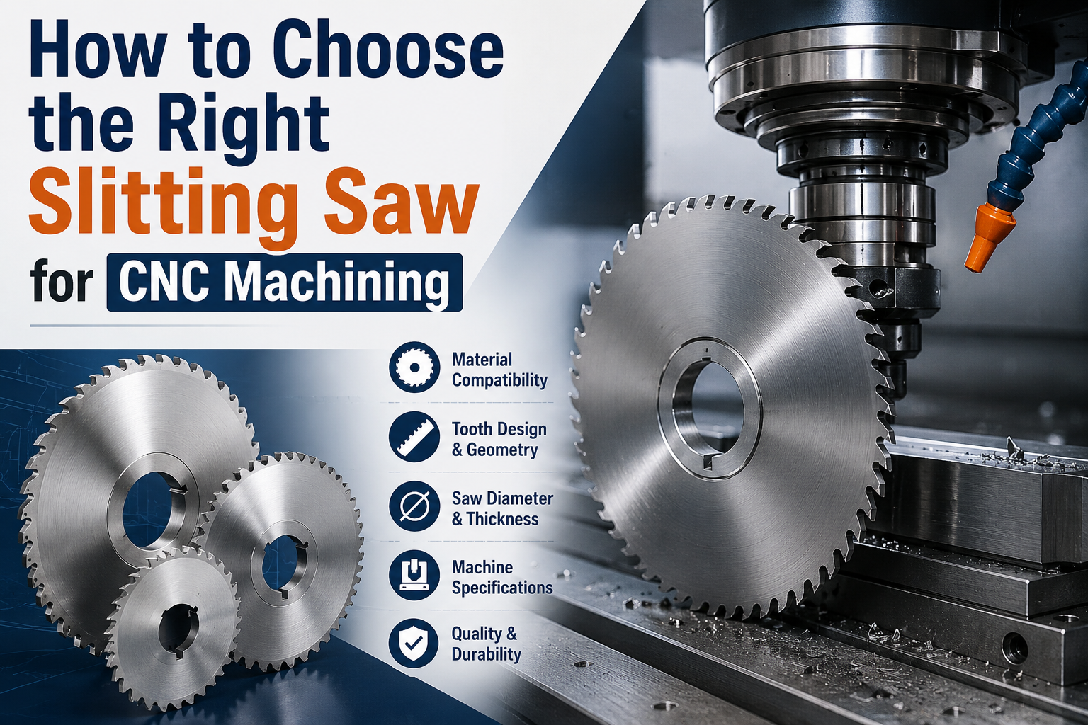



















































































































































































































































































































































































































































































































































































































































































































































































































































































































































































































































































































































































































































































































































































































































































































































How to Choose the Right Slitting Saw for CNC Machining

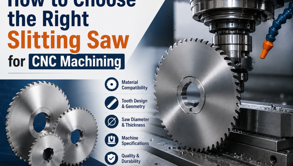
Precision CNC machining centers handle tight-tolerance slotting, grooving, and parting operations daily. When machining deep, narrow slots, traditional solid-carbide end mills frequently deflect, vibrate, or snap under side loads. To overcome these mechanical limits, CNC programmers and machinists install a specialized slitting saw on a rigid toolholder arbor.
Selecting the correct circular slitting saw requires evaluating several interdependent variables: blade substrate material, tooth geometry, blade thickness, arbor rigidity, and workpiece metallurgy. A properly matched saw cuts clean, narrow slots with parallel sidewalls, eliminates secondary deburring passes, and extends tool life across demanding production runs.
Tooling manufacturers like Maxwell supply custom-ground, high-precision slitting cutters manufactured to strict DIN 1837 and DIN 1838 industrial standards. Whether you cut aluminum heatsinks, slit steel clamping collars, or mill keyways into heat-treated alloy shafts, following a structured selection methodology ensures predictable results on your CNC mill.
1. Select the Right Blade Substrate Material
The first critical step involves matching the blade material to your machine’s rigidity, spindle speed capabilities, and workpiece hardness.
Substrate Selection:
├─► High-Speed Steel (HSS / M2) ──► High Toughness | Resists Chipping | Low-to-Medium Speeds
├─► Cobalt HSS (M35 / M42) ──► Heat Resistant | Moderate Speeds | Tough Alloys / Stainless
└─► Solid Carbide / Tipped ──► Maximum Rigidity| High Speeds | Production Runs / Hard Metals
High-Speed Steel (HSS / M2)
HSS blades offer exceptional toughness and flexibility. They absorb mechanical vibration and handle interrupted cuts without chipping.
- Best For: Prototyping, small batch runs, mild carbon steels, non-ferrous metals, and older CNC machines with minor spindle play.
- Hardness: Typically 63–65 HRC.
Cobalt HSS (M35 and M42)
Cobalt-alloyed high-speed steels contain 5% to 8% cobalt, raising the red-hardness of the cutting teeth. They resist heat buildup when cutting materials that work-harden quickly.
- Best For: Austenitic stainless steels (304, 316), high-tensile alloy steels, and titanium alloys.
- Hardness: Typically 65–68 HRC.
Solid Carbide and Carbide-Tipped
Solid carbide delivers maximum hardness and torsional rigidity. Carbide allows CNC programmers to run significantly higher surface speeds (SFM), which shortens cycle times on high-volume production lines. However, carbide is brittle and shatters if exposed to arbor runout or sudden chatter.
- Best For: Modern, rigid CNC machining centers cutting cast iron, hardened steels, abrasive composites, and high-volume aluminum parts.
2. Match Tooth Form and Pitch to the Cut Depth
Choosing the correct tooth count and tooth profile prevents chip packing—the primary cause of broken slitting saws.
DIN Standards for Tooth Forms:
┌─► DIN 1837 (Fine Pitch / Profile A & B) ──► Thin Sheets | Shallow Slots | Fine Finish
└─► DIN 1838 (Coarse Pitch / Profile C) ──► Deep Slots | Solid Stock | Large Chip Gullets
DIN 1837 vs. DIN 1838 Standards
- DIN 1837 (Fine Tooth Form): Features straight or slightly radiused tooth forms with shallow gullets and high tooth counts. This profile distributes the cutting load across multiple teeth simultaneously. Use DIN 1837 saws for shallow slotting, thin-walled tubing, and delicate workpieces.
- DIN 1838 (Coarse Tooth Form): Features curved or pegged teeth (Profile C) with large chip pockets. These wide gullets allow long, curly chips to curl and evacuate freely without jamming in the cut. Use DIN 1838 saws for deep slotting and solid bar cutoffs.
The “Three-Tooth Rule”
Always maintain a minimum of two to three teeth in continuous contact with the workpiece at all times. If only one tooth contacts the material, the tooth experiences severe impact shocks that cause chipped cutting edges. Conversely, having too many teeth in a deep cut packs chips into the gullets, generating extreme friction that welds the saw into the workpiece.
3. Choose the Correct Saw Body Geometry
The side profile of the saw body determines whether the blade clears the slot walls cleanly or rubs and overheats.
Blade Body Types:
├─► Plain Slitting Saw ──► Flat sides | Shallow depths only | Light parting
├─► Hollow-Ground (Concave) ──► Tapered sides | Clearance for medium-depth slots
└─► Side-and-Face / Staggered ──► Cutting teeth on sides | Deep slots | High chip loads
| Saw Type | Body Design | Primary Use-Case |
|---|---|---|
| Plain Metal Saw | Flat, parallel side faces | Shallow slots (depth < 2x blade thickness) |
| Hollow-Ground Saw | Concave dish grind from teeth to bore | Medium slots; prevents sidewall rubbing |
| Staggered-Tooth Saw | Alternating left/right cutting teeth | Deep slots; cuts on periphery and both sides |
For deep slotting operations, staggered-tooth side-and-face saws cut chips into smaller, manageable segments. The alternating teeth cut clearance on both walls, preventing binding during deep radial engagement.
4. Calculate Proper Diameter, Thickness, and Arbor Sizing
Rigidity dictates saw performance on CNC equipment. Always select the smallest outer diameter (OD) and thickest blade body that the part geometry permits.
Keep the Diameter as Small as Possible
Large-diameter saws require lower rotational speeds and exhibit greater lateral flexibility. Calculate your required cut depth plus the arbor collar clearance, then choose the smallest standard saw diameter that clears the clamp:
Minimum Saw Radius=Depth of Cut+Arbor Collar Radius+Safety Clearance (2–3 mm)
Maximize Arbor Hub Collar Support
Use large-diameter, precision-ground arbor drive collars. Supporting the saw blade with collars that extend close to the tooth gullets dramatically stiffens the blade body, suppresses harmonic chatter, and prevents blade flutter at high feed rates.
Industrial manufacturers such as Maxwell Slitter Industries precision-grind blade mounting bores to tight H7 tolerances, ensuring true concentric seating on precision CNC arbors.
5. Implement Proven CNC Speeds, Feeds, and Cutting Strategies
Applying the right programming strategy transforms saw performance from unreliable to highly efficient.
Surface Speed and Feed Guidelines
- Mild Steels: Run HSS at 20–30 m/min; run Carbide at 80–120 m/min.
- Aluminum Alloys: Run HSS at 80–150 m/min; run Carbide at 200–500 m/min.
- Stainless Steels: Run Cobalt (M42) at 12–18 m/min with steady, positive feed per tooth (0.015–0.03 mm/tooth) to prevent work-hardening.
Program Climb Milling on Rigid CNCs
Always program climb milling (down milling) on modern CNC machining centers. Climb milling enters the cut at maximum chip thickness and exits at zero thickness. This approach directs cutting forces down into the machine table, minimizes tooth rubbing, and delivers a superior sidewall surface finish. Only use conventional (up) milling on older manual machines that possess significant backlash.
Direct High-Pressure Coolant to the Cut Zone
Position high-pressure coolant nozzles directly into the slot at the point where the saw teeth enter the cut. Flooding the slot flushes chips out of the cut zone and cools the blade perimeter, preventing thermal expansion that causes binding.
Selection Checklist
Before loading a slitting saw program into your CNC control, verify these parameters:
- Substrate: Selected HSS for toughness or Carbide for high-speed rigidity.
- Standard: Verified DIN 1837 for thin walls or DIN 1838 for deep cuts.
- Engagement: Confirmed 2 to 4 teeth engage the cut simultaneously.
- Side Clearance: Selected hollow-ground or staggered teeth for deep slots.
- Runout: Measured total radial and axial arbor runout below 0.005 mm (0.0002 in).
Frequently Asked Questions (FAQs)
1. How do I calculate the correct tooth count for a slitting saw?
To find the right tooth count, calculate the contact arc length inside the workpiece. Select a tooth pitch that keeps between two and four teeth engaged in that arc throughout the cut. For thin sheet stock, choose high tooth counts (DIN 1837); for solid blocks with long contact arcs, choose low tooth counts (DIN 1838) to provide sufficient chip clearance.
2. Why does my slitting saw vibrate or produce poor sidewall finish?
Vibration occurs when the arbor runs out of true, the blade diameter is too large for the cut depth, or arbor clamping collars are too small. To eliminate vibration, inspect arbor runout with a dial test indicator, install larger drive collars, and switch to climb milling with a steady, positive feed rate.
3. Can I use a slitting saw to cut stainless steel on a CNC mill?
Yes. When cutting stainless steel, use an M42 cobalt or solid carbide saw with a hollow-ground or staggered-tooth profile. Run low surface cutting speeds (12–18 m/min for cobalt), maintain a positive feed per tooth (0.02 mm/tooth) to avoid rubbing, and apply flood coolant directly into the slot.
4. What causes a slitting saw blade to dish or warp during operation?
Dishing happens when excessive heat builds up in the cut, causing the thin outer rim to expand faster than the cooler center hub. Chip recutting, lack of side clearance, dull teeth, and insufficient coolant delivery all generate excessive friction that warps the blade body.