Charles Spinelli Unlocks the Secrets of Designing a
May 19, 2025What to Expect from a Financial Advisor in
May 17, 2025Steven Rindner On Impact of Weather Conditions in
May 15, 2025Is Post-Op IV Ozone Therapy Useful for Joint
May 03, 2025How Do You Take Care of Your Vehicle
May 03, 2025Does Oxygen Facial Reduce Large Pores Too?
May 03, 2025Discover the Bold Streetwear Power of the Iconic
May 03, 2025Choose VIP Travel Agency for Luxury Adventures
May 02, 2025Why Choose HydraFacial for Flawless Skin in Dubai?
May 02, 2025Bitachon for Beginners: A Quick Guide
May 02, 2025Top Skin Whitening Treatments in Dubai: A Quick
May 02, 2025Download GB WhatsApp APK – Updated Version (2025)
May 02, 2025Top Guma – Affordable Tires for Every Car,
May 02, 2025Top Guma – Wide Selection of Car Tires
May 02, 2025GV GALLERY® || Raspberry Hills Clothing Store ||
May 02, 2025How Does Wegovy Injections Compare to Saxenda?
May 02, 2025Resume writing services – hirex
May 02, 2025Finding the Best Naperville Fence Company for Your
May 02, 2025Unlock the Power of Numbers with a Numerology
May 02, 2025Title: Top Online Game Genres to Watch in
May 02, 2025Who Is the Biggest Enemy of Lord Vishnu
May 02, 2025Reliable Manchester to Airport Taxi Service – Fixed
May 02, 2025Complete Greenhouse Solutions by EKO TEPLYTSIA Kyiv
May 02, 2025How Henceforth Leads as a Premier App Development
May 02, 2025High-Quality Jewellery Design CAD Files Online
May 02, 2025Tassie-Tough MTA: Where Stability Meets Progress
May 02, 2025The Ultimate Guide to ISO Training: Top Management
May 02, 2025Crafting Cute and Creative Party Decor for Every
May 01, 2025Halal Certification: What It Is and Why It’s
May 01, 2025How Professional CIPD Help Can Boost Your Academic
May 01, 2025Choosing the Right Retirement Homes in Sydney: A
May 01, 2025Drive in Style with Premium Android Car Radios
May 01, 20256+ Years of Quality Android Car Stereo Installations
May 01, 2025Reliable Romiley to Manchester Airport Taxi Service
May 01, 2025United States Semiconductor Market Size & Share |
May 01, 2025Masters in Ireland for Indian Students: Best IT
May 01, 2025One Goal. One Result. The Best CUET Coaching
May 01, 2025Top Castles and Palaces to Visit in Hungary
May 01, 2025How to Choose the Best PPC Management Company
May 01, 2025Living Room Design Tips from a Knoxville Remodeling
May 01, 2025Are One-Size-Fits-All Marketing Services Worth It?
May 01, 2025Badson US || Official Badson Clothing Store ||
Apr 30, 2025Bajaj Pulsar NS 160: The Perfect Bike for
Apr 30, 2025محل عطور فاخر يقدم أجود الروائح وتجربة تسوق
Apr 30, 2025The Timeless Allure of Agarwood Oud
Apr 30, 2025Hire Laravel developer at affordable price
Apr 30, 2025Is ClearLift Laser Suitable for Mature Skin?
Apr 30, 2025Is PDO Mono Threads Right for Your Skin?
Apr 30, 2025ISO 45001 Training: Essential Steps for a Safer
Apr 30, 2025Trusted Mobile Notary in Pasadena – Fast &
Apr 30, 2025Proven Facts to Fix QuickBooks Error Code 15276
Apr 30, 202510 Compelling Reasons to Buy Space Binoculars
Apr 30, 2025Why Are i7 Laptops Still the Top Pick
Apr 30, 2025What Is Rhinoplasty and How Does It Work?
Apr 30, 2025Unlocking Pharma Success with Real World Data in
Apr 29, 2025Top SEO Services in Los Angeles: Boost Your
Apr 29, 2025Does ClearLift Laser Work on Acne Scars?
Apr 29, 2025Is Hair Transplant Effective for Balding Men?
Apr 29, 2025Insurance Company in Abu Dhabi – Tailored Solutions
Apr 29, 2025GB WhatsApp APK Download 2025 (Latest Version)
Apr 29, 2025Is Fat Injections Better Than Fillers for Facial
Apr 29, 2025Reliable Taxi from Stockport to Manchester Airport
Apr 29, 2025Luxury Sprinter Van Limo Service – Comfort, Style
Apr 29, 2025Our Uniting Classic USA Craft with Chrome Heart
Apr 29, 2025How a Web Development Company Builds Websites That
Apr 29, 2025How a Moisture Analyzer Improves Product Quality
Apr 29, 2025Reporting CSRD : Automatisez vos processus
Apr 29, 2025Top 10 Features to Look for in a
Apr 29, 2025Top Platforms to Sell Google Play Gift Card
Apr 29, 2025Dust Collector Manufacturer in India
Apr 29, 2025Pharmacovigilance in New Zealand – DDReg Pharma
Apr 29, 2025The #1 Natural Snoring Solution — NiteHush Pro
Apr 29, 2025Understanding Mental Health: A Beginner’s Guide
Apr 29, 2025How to Choose Perfume Based on Personality?
Apr 29, 2025Pharma Commercial Analytics and Consulting in 2025
Apr 29, 2025Best Airport Limo Service – Comfort, Luxury, and
Apr 29, 2025Fast Car Battery Replacement in Abu Dhabi –
Apr 29, 2025Mobile Tyre Repair in Abu Dhabi: 24/7 Roadside
Apr 29, 2025Complete Guide to Car Towing Services : 24/7
Apr 28, 2025Why Companies Need a Better Strategy for a
Apr 28, 2025Top Features to Look for When Developing Book
Apr 28, 2025Southampton Limo Service | Luxury Car & Airport
Apr 28, 2025Black Leather Coat for Women for Effortless Winter
Apr 28, 2025Top 7 Secrets to Extend Your Car AC
Apr 28, 2025Taxi from Glasgow to Manchester Airport | Affordable
Apr 28, 2025Kundali Houses Explained: Your Horoscope Secrets
Apr 28, 2025Top 10 Business Schools in Jaipur You Shouldn’t
Apr 28, 2025Why Invest in Property in Sector 10 &
Apr 28, 2025How to Choose the Right Solar Battery for
Apr 28, 2025Is Freckles and Blemishes Treatment Permanent?
Apr 28, 2025Unique Themes for Adelaide Wedding Receptions
Apr 28, 2025How to Grow Your Instagram Followers: A Strategic
Apr 28, 2025Book Trusted Newark Airport Limo Services | Noor
Apr 27, 2025GB WhatsApp APK (2025) – Latest Version Download
Apr 27, 2025Badson US || Official Badson Clothing Store ||
Apr 27, 2025Why Corteiz Hoodie is Perfect for Everyone
Apr 26, 2025Does Orlebar Brown Clothing Provide Fabric of the
Apr 26, 2025The Loverboy Hat: A Revolutionary Symbol in the
Apr 26, 2025In Glock We Trust Shirt has the most
Apr 26, 2025Why Sp5der Hoodie Is The Best Accessory You
Apr 26, 2025The Emergence of Hellstar Clothing in the Fashion
Apr 26, 2025Serenede jeans– Top Quality Brand
Apr 26, 2025Everything You Need to Know About Swiss Oud
Apr 26, 2025Top 8 Hayati Pro Max 6000 Flavours that
Apr 26, 2025Everything You Need to Know About Premium Oud
Apr 26, 2025Les meilleures saveurs de vapotage de Ghost Pro
Apr 26, 2025Complete Information on Original Oud Attar and Its
Apr 26, 2025De beste vaping smaken van Ghost Pro 3500
Apr 26, 2025Everything You Need to Know About White Oud
Apr 26, 2025Everything You Need to Know About Deer Musk,
Apr 26, 2025Everything You Need to Know About Oud Hindi:
Apr 26, 2025Unlock Your Week: Aquarius Weekly Horoscope Guide
Apr 26, 2025Does Acne Scar Treatment Lighten Dark Marks?
Apr 26, 2025Affordable Gastric Bypass Surgery for Weight Loss in
Apr 25, 2025The Pros and Cons of Static Site Generators
Apr 25, 2025Affordable Men’s Fashion: Best Stores to Shop
Apr 25, 2025Boost Your BPO Performance with Smart CRM Software
Apr 25, 2025How to Raise Emotionally Strong Kids as a
Apr 25, 2025Gallery Dept T-Shirt: Streetwear
Apr 25, 2025How to Make Your Hair Look Shiny and
Apr 25, 2025Is Your Hampshire Website Mobile-Friendly?
Apr 25, 2025Top 10 Electrical Companies in Dubai
Apr 25, 2025Unlock the Web with CroxyProxy – The Ultimate
Apr 25, 2025What are the common mistakes that you have
Apr 25, 2025How to Maintain Non-Surgical Hair Replacement?
Apr 25, 2025The Benefits of Hiring a Local Canberra Wedding
Apr 25, 2025Need a Blocked Sink Fix in Stourbridge? Contact
Apr 25, 2025Boost Your Business with Local SEO Services in
Apr 24, 2025San Diego SEO Services for Higher Rankings &
Apr 24, 2025Real Estate App Development: Essential to Build a
Apr 24, 2025Empyre | Empyre Jeans & Pants | Official
Apr 24, 2025The Rise of Natural Skin Care: Is Makeup
Apr 24, 2025Level Up Your Irrigation Game with These Top-Rated
Apr 24, 2025Soil Pipe Blocked Again? Here’s How to Solve
Apr 24, 2025Struggles Faced by New Moms & Tips to
Apr 24, 2025The Best Passive Real Estate Investment Options in
Apr 24, 2025The Pros and Cons of Investing in Custom
Apr 24, 2025Website Design Pitfalls for Small Businesses: How to
Apr 24, 2025The Role of SEO Tools in a Data-Driven
Apr 24, 2025Choosing the Right Electrician in Adelaide
Apr 24, 2025How Retargeting Can Drive Conversions and Boost ROI
Apr 24, 2025How to Choose the Right Disability Support Provider
Apr 24, 2025Private Taxi from London to Manchester Airport –
Apr 24, 2025How Technology is Changing the Path of Marriage
Apr 24, 2025Mukhyamantri Kisan Kalyan Yojana
Apr 24, 2025Is Organic Pumpkin Peel Better Than Chemical Peels?
Apr 24, 2025Building Smart Chatbots with PHP for Better UX
Apr 24, 2025Professional Help With Writing Thesis for Students
Apr 24, 2025The Kashyap Samhita and the Role of CSS
Apr 24, 2025NYC Cleaning & Maintenance – Trusted Experts for
Apr 23, 2025The Ultimate Guide to : A Luxurious Travel
Apr 23, 2025Realme 2025 Vision: AI Smartphones, & What’s Next
Apr 23, 2025How to Save Money on Car AC Repairs:
Apr 23, 2025Elevating Hygiene Standards in Every Space
Apr 23, 2025Top Certifications Pursue Alongside Your MS in Data
Apr 23, 2025Why Gold Bracelets Are a Must-Have in Every
Apr 23, 2025Smart Property Management Across the New York Metro
Apr 23, 2025Everything You Need to Know About Tummy Tuck
Apr 23, 2025Leo Daily Horoscope – Your Complete Guide
Apr 23, 2025Why Sure Shade Is the Leading External Venetian
Apr 23, 2025The Truth About Finding a Limo Service That’s
Apr 23, 2025Top Benefits of Virtual Office Valdosta GA for
Apr 23, 2025Your Guide to Luxury and Reliability in Northern
Apr 23, 2025UnitConnect: Simplify Commercial Property Management
Apr 23, 2025Smarter Real Estate Tools with UnitConnect Software
Apr 23, 2025How to Safely Overclock with the Intel Overclocking
Apr 23, 2025What Interest Rate Hikes Really Mean for Stock
Apr 23, 2025The Powerful Ruby: Discover the Top Ruby Gemstone
Apr 23, 2025Affordable Taxi from London to Manchester Airport
Apr 23, 2025Unlocking the Secrets of the Triangle in Palmistry
Apr 23, 2025Best IT Services in Oakland for Startups &
Apr 23, 2025How do I speak to someone at Breeze?
Apr 23, 2025How do I talk to a real person
Apr 23, 2025Buy Get Well Soon Flower Online for Her
Apr 23, 2025California Needs Drivers: Apply Now for the Best
Apr 23, 2025Botox Isn’t Just for Women: Men Embrace a
Apr 23, 2025Master Tableau with Expert Tableau Assignment Help
Apr 23, 2025The Rise of Cortiez Cargos: A Streetwear Staple
Apr 23, 2025Essentials Shorts: The Perfect Blend of Comfort and
Apr 22, 2025Why Choosing a Content Writing Agency in Houston:
Apr 22, 2025How to Use Your Intuition to Create Magnetic
Apr 22, 2025Mastering Evidence-Based Practice in NURS-FPX 4030
Apr 22, 2025Is Male Hair Loss Fixed by Best Trichologists?
Apr 22, 2025Food Safety Leader: FSSC 22000 Lead Auditor Course
Apr 22, 2025Top 10 Things to Know Before Visiting Maine
Apr 22, 2025Top Benefits of Installing Sliding Glass Doors in
Apr 22, 2025Book Trailer Services: A Smart Way to Promote
Apr 22, 2025Everything You Need to Know About Buying a
Apr 22, 2025Trusted Experts for Quality Cleveland Roof Repairs
Apr 22, 2025ISO 9001 Lead Auditor Training in Bangalore
Apr 22, 2025Broken Promises and the Healing Power of God
Apr 22, 2025How to Choose the Best Body Spa in
Apr 22, 2025Originalteile und Nachbauteile bei ORAP GMBH
Apr 22, 2025Original- und Nachbauteile direkt vom Fachhändler
Apr 22, 2025Ihr Partner für hochwertige Autoteile im Groß- und
Apr 22, 2025Get Your Towbar Fitted by Experts in Bishop’s
Apr 22, 2025How Body Pillow Shapes Affect Your Spine, Joints,
Apr 22, 2025The Role of Solar Power in Sustaining Military
Apr 22, 2025Which Areas in Dubai Have the Most Promising
Apr 22, 2025Why ISO 14001 Lead Auditor Training Could Be
Apr 22, 2025Discover New Builds in Easton: Modern Living
Apr 22, 2025Tips to choose the best kids backpack
Apr 22, 2025How Is G Cell Treatment Different From PRP?
Apr 22, 2025Which Football League Offers the Best Tactical Depth
Apr 22, 2025Is Renting or Buying a Home Better for
Apr 22, 2025A Smarter Way to Trade Stocks, Forex, and
Apr 22, 2025Graceful Church Suits Every Woman Should Own
Apr 22, 2025Recruitment agency in delhi- hirex
Apr 22, 2025Badson US || Official Badson Clothing Store ||
Apr 22, 2025Corteiz Clothing UK RTW Official Store | Cortiez
Apr 21, 2025Explore Livingston Park and Cabin Rentals in Texas
Apr 21, 2025Best Peking Duck and Curry Crab in Houston
Apr 21, 2025Finding the Right Pet Veterinary Clinic in Qatar
Apr 21, 2025Maximize Space and Style with Stackable and Metal
Apr 21, 2025Embrace the East with Every Sushi Roll at
Apr 21, 2025Sushi Point: Discover the True Spirit of Sushi
Apr 21, 2025Authentic Eastern Flavors, Perfected at Sushi Point
Apr 21, 2025How Do i5 and i7 Processors Compare for
Apr 21, 2025Samsung A26 Price in Pakistan – Specs You
Apr 21, 2025Technical SEO Done Right: Tips from a San
Apr 21, 2025Affordable SEO Services: A Comprehensive Guide
Apr 21, 2025Does Fat Injections Help Sculpt the Body?
Apr 21, 2025MBA in HR Management in Jaipur: Classroom to
Apr 21, 2025Everything You Need to Know About Liposuction in
Apr 21, 2025Find out what colleges in Jaipur offer mechanical
Apr 21, 2025Private Taxi from Blackpool to Manchester Airport –
Apr 21, 2025Intel HD Graphics vs. Dedicated GPUs: What’s Better?
Apr 21, 2025StrikeIT: Trusted SEO Company in Lucknow
Apr 21, 2025Why Split & Multi-Split ACs Suit Homes and
Apr 21, 2025Does Botox for Sweaty Gland Block All Sweat?
Apr 21, 2025Best Custom Patches in Malaysia
Apr 21, 20255 Important Health Benefits Of The Shecup Silicone
Apr 21, 2025Part-Time Jobs in Germany for International Students
Apr 21, 2025Affordable Taxi from Blackpool to Manchester Airport
Apr 20, 202570 Inch Bed Frame Maintenance Tips: to Keep
Apr 19, 2025The Beauty of Handmade Shell Jewellery
Apr 19, 2025Exotic Ride Rent A Car in Dubai
Apr 19, 2025WordPress Experts for High-Converting Sites
Apr 19, 2025Key Benefits of Combining Your MOT Test and
Apr 19, 2025Best gold buyers |Sell gold for cash |Hindustan
Apr 19, 2025Statistics Assignment Help – Expert Stats Solutions
Apr 18, 2025Mertra Clothing || Sale Up To 40% Off
Apr 18, 2025Rhinoplasty Cost in Lahore Explained: Find the Right
Apr 18, 2025E-Commerce and Q-Commerce: Compare all Details
Apr 18, 2025Ukraine Premier Vascular Center – Discover AngioLife
Apr 18, 2025Trusted Vascular Solutions in Ukraine
Apr 18, 2025Best Ethernet Cable for Gaming: A Perfect Guide
Apr 18, 2025Sector 140A Noida: A Prime Location for Retail
Apr 18, 2025Unlocking the Power of Ethernet: How It Fuels
Apr 18, 202515 Budget-Friendly Home Remodeling Ideas That Make a
Apr 18, 2025What Should You Know Before Getting Laser Hair
Apr 18, 2025Private Taxi from Birmingham to Manchester Airport
Apr 18, 2025Not Just Pretty – Design a Patio That
Apr 18, 2025Understanding Your CIBIL Score and Its Importance
Apr 18, 2025How Well Does the Intel Arc GPU Perform
Apr 18, 2025Vicdigit Technologies
Apr 18, 2025The Ultimate Guide to Corrugated Boxes
Apr 18, 2025Best Ethernet Cable for Gaming: A Perfect Guide
Apr 17, 2025High-Quality Seat Covers and Mats for Your Car
Apr 17, 2025How to Prepare for Freckles and Blemishes Treatment?
Apr 17, 2025The Top Reasons to Choose Lake Tahoe Boat
Apr 17, 20252031 Industry Report: Key Drivers Fueling the Data
Apr 17, 20259 Scenes Where i7 Laptops Are the Better
Apr 17, 2025Smart Features of Tapmoon Token That You Need
Apr 17, 2025Process Mining Software Market Size to Skyrocket by
Apr 17, 2025Explore a Wide Selection of Smoking Essentials at
Apr 17, 2025Section 125 Tax Savings Plans: What Every Company
Apr 17, 2025Targeted Musculoskeletal Treatment in Edinburgh
Apr 17, 2025How to Layer Skincare with Acne Scar Treatment?
Apr 17, 2025Pizza Novato Is a Must-Try Culinary Experience
Apr 17, 2025How Cloud Solutions in Dubai Are Enabling Remote
Apr 17, 2025How to Get Ready for Your Anti-Aging Facelift
Apr 17, 2025Reliable Solar Panels and Systems for Your Home
Apr 17, 2025Should You Fight for More Disability Benefits and
Apr 17, 2025Modular Office Workstations To Boost Productivity
Apr 17, 2025Find Your Ideal Tech Candidate with EvoTalents
Apr 16, 2025How to Buy a Business in Florida: A
Apr 16, 2025Empowering the Next Generation of Leaders at Lviv
Apr 16, 2025A Vision for the Future of Ukrainian Education
Apr 16, 2025AWS vs. Azure vs. Google Cloud for Hosting
Apr 16, 2025How IV Ozone Helps You Recover Faster from
Apr 16, 2025Why Laundry Services Are Smart for Your Busy
Apr 16, 2025How Hiring an SEO Expert Pays Off for
Apr 16, 2025Decorative LED Lighting for Garden, Backyard & Home
Apr 16, 2025Create Atmosphere with LED Trees & Solar Lights
Apr 16, 2025Comprehensive SEO Services in Dubai: From On-Page to
Apr 16, 2025The Future of Web Design and What It
Apr 16, 2025Transform Your Journey with DNA-Guided Weight Loss
Apr 16, 2025Embrace Wellness at Your Doorstep: The Rise of
Apr 16, 2025Silver Wound Dressing Market Outlook 2031
Apr 16, 2025Immune Checkpoint Inhibitors Market Analysis 2033
Apr 16, 2025Chronic Disease Management Market Disruption
Apr 16, 2025Medical Gas Equipment Market Strategy Guide
Apr 16, 2025How FSM Software Enhances Technician Productivity
Apr 16, 2025Top 5 Online BIM Courses in 2025: Upskill
Apr 16, 2025Gifts for Boyfriend: What Women Are Asking Online?
Apr 16, 2025Top Real Estate Broker Software to Power Smarter
Apr 16, 2025How a Psychiatrist Can Help You Improve Mental
Apr 16, 2025How to Dress Up or Down the Essentials
Apr 15, 2025How to Choose the Best Audio Recorder for
Apr 15, 2025Why Now Is the Best Time to Explore
Apr 15, 2025Global 3D Printing Gases Market Set to Soar
Apr 15, 2025Mitolyn in New York: Ultimate Guide Weight Loss
Apr 15, 2025Top Reasons to Choose a 4-Star Hotel in
Apr 15, 2025Global Nutritional Analysis Market Set to Soar by
Apr 15, 2025How to Use GMB Everywhere? Complete Guide to
Apr 15, 2025From Romantic Getaways to Paint Nights – Gifting
Apr 15, 2025Top Brightening Face Scrubs to Try in 2025
Apr 15, 2025Vibe Experience Gifts – Adventures, Art, Food &
Apr 15, 2025Taking Care Of Health & Beauty at Our
Apr 15, 2025The Future of Healthcare: Why AI Mobile Apps
Apr 15, 2025Does Body Filler Treatment Require Anesthesia?
Apr 15, 2025Milk Powder Market : Key Drivers, Regional Insights
Apr 15, 2025Benefits of Choosing a Birthing Center in Tulsa
Apr 15, 2025Dump Trucks & Mining Trucks Market : Key
Apr 15, 2025How the Broken Planet Hoodie Scuplts Distinction
Apr 15, 2025Imported Japanese Diapers & Baby Food at Kurumi
Apr 15, 2025Your Trusted Online Shop for Baby Goods from
Apr 15, 2025Understanding the Role of a Neurologist in Treating
Apr 15, 2025Why You Should Host Your Next Event at
Apr 15, 2025Styling Tips for Korean-Inspired Outfits
Apr 15, 2025Anti-Aging Tips Using Natural Ingredients
Apr 15, 2025How’s the Intel i7 vPro Platform Supporting Remote
Apr 15, 2025Recruitment agency in delhi – hirex
Apr 15, 2025Is Natural Cotton Batting the Best Choice for
Apr 15, 2025Private Taxi from Leeds to Manchester Airport –
Apr 15, 2025Best PPC Company in India for Better ROI
Apr 15, 2025How a Top Video Production Agency is Scooping
Apr 15, 2025B2B Payments in 2025: Emerging Trends and Payment
Apr 15, 2025Navigating Global Trade: How Dubai Became a Shipping
Apr 15, 2025Warren Lotas Hoodie: Exclusive Streetwear
Apr 15, 2025Electric Kick Scooter Market : Insights & Forecast
Apr 15, 2025Automotive Paints Market : Insights & Forecast to
Apr 15, 2025Causes of Irregular Periods in Your 30s
Apr 15, 2025Avoiding Common Mistakes When Applying for a Vehicle
Apr 15, 2025Find Premium Home, Beauty, and Health Products at
Apr 15, 2025Shop Quality Products for Every Aspect of Your
Apr 15, 2025Daily Current Affairs in Telugu
Apr 15, 2025Reputable Car Engine Repair: Best Service Practices
Apr 14, 2025MRCOG Part 1 Dates Revealed: What Every Candidate
Apr 14, 2025Is Your Office Lock Jammed? Hire a Locksmith
Apr 14, 2025AZ-104 Exam Dumps: Microsoft Azure Administrator QnA
Apr 14, 2025Why Choosing the Right Audit Company Matters for
Apr 14, 2025Business Travel to Kenya: Visa Rules, Validity, and
Apr 14, 2025Why Spaghetti Strap Blouses Are a Must-Have in
Apr 14, 2025Cheap Taxi from Leeds to Manchester Airport with
Apr 14, 2025The Ultimate Guide to Local SEO for Small
Apr 14, 2025Free 6 Tips: Learn How to Use a
Apr 14, 2025Top Crops for Small-Scale Farming: A Brief Guide
Apr 14, 2025What Are the Key Pieces of Computer Networking
Apr 14, 2025Best Kodi Alternative for iOS in 2025
Apr 14, 2025How do you find the perfect nose shape
Apr 14, 202511 iPhone 12 Case Cover for Nature Lovers
Apr 14, 2025Where to Buy Snore Stop Products Online and
Apr 14, 2025Top Reasons to Choose Thailand for Your Next
Apr 14, 2025Coffee Beans Market is Set to Witness Significant
Apr 14, 2025Snack Food Market is Projected to Reach USD
Apr 14, 2025Vegetable Oil Market to Reach USD 790,878.03 Mn
Apr 14, 2025Abrasive Market Will Achieve USD 63.79 Billion by
Apr 14, 2025Instant wellness? Try home-based IV therapy in Dubai
Apr 14, 2025Are There Programs That Offer Housing Help for
Apr 14, 2025How Noise-Canceling Earbuds Enhance Your Focus
Apr 14, 2025Steps to Purchase from Sp5der Hoodie Brand
Apr 13, 2025MERTRA || Shop Now Mertra Mertra Clothing ||
Apr 13, 2025Understanding Different Types of Teens Counselling
Apr 13, 2025Experience at Hellstar T-Shirt Online Official Store
Apr 13, 2025MERTRA || Shop Now Mertra Mertra Clothing ||
Apr 13, 2025Top 10 Natural Remedies for Insomnia That Help
Apr 13, 2025Where Purpose Meets Action: A Look at Local
Apr 13, 2025How to Find the Right Healthcare Support During
Apr 13, 2025LANVIN® || Lanvin Paris Official Clothing || New
Apr 12, 2025Bape Shirt: Thoughtful Design for Comfort and Style
Apr 12, 2025Ultimate Tips To Boost Your Academic Scores in
Apr 12, 2025The Top 7 Reasons Why Your Car Needs
Apr 12, 2025South Africa Visa Processing Time: What to Expect
Apr 12, 2025Rehydrate, Energize, Glow – All with IV Therapy
Apr 12, 2025Falsely Accused of Domestic Violence? How to Find
Apr 12, 2025Corteiz ® | CRTZRTW Official Website || Sale
Apr 12, 2025Simplify Complex Tasks with MATLAB Assignment Help
Apr 12, 2025Exploring Bare Metal Cloud Market Growth: Trends &
Apr 11, 2025The Ultimate Guide to Quick and Easy Car
Apr 11, 2025Why Use React Helmet for Managing Page Titles
Apr 11, 2025Best Pool Parties in Dubai and Best Beach
Apr 11, 2025Finding the Best Psychologist in Dubai A Guide
Apr 11, 2025Look for Irish Assignment Help Services to Ensure
Apr 11, 2025¿Vale la pena el trasplante de pelo precio?
Apr 11, 2025Tired of Hair Loss? Discover the Magic of
Apr 11, 2025The Importance of Tile Glue and Waterproofing in
Apr 11, 2025Best Therapist in Dubai: Your Guide to Anxiety
Apr 11, 2025Transforming Dubai’s Infrastructure: An Overview
Apr 11, 2025Affordable Stockport Taxis – Book Your Reliable Ride
Apr 11, 2025Handcrafted Eco Baby Toys That Promote Learning |
Apr 11, 2025Saudi Arabia Chiller Market Growth, Key Trends &
Apr 11, 2025Discover Unmatched Comfort at the Best Resorts in
Apr 11, 2025Oman Air Conditioner Market Growth, Key Trends &
Apr 11, 2025Smart Camera Market : Key Drivers, Regional Insights
Apr 11, 2025Middle East and Africa Press Fit Connector Market
Apr 11, 2025Pranav International Oil Mill Machinery
Apr 11, 2025North America Protein Market : Key Drivers, Regional
Apr 11, 2025Do Urinary Tract Infections Lead to Kidney Damage?
Apr 11, 2025Vegan Food Market: Key Drivers, Regional Insights &
Apr 11, 2025Seafood Market : Key Drivers, Regional Insights &
Apr 11, 2025United States Small Kitchen Appliances Market : Key
Apr 11, 2025Mengapa Ligue 1 Jadi Tambang Emas bagi Pemandu
Apr 11, 2025Cortiez Cargos: The Streetwear Staple You Need in
Apr 11, 2025Google Shopping Feed Simprosys – Sync Inventory Fast
Apr 11, 2025Essentials Shorts: Comfort, Style, and Versatility
Apr 11, 2025Protect London® | Protect LDN Clothing Store |
Apr 11, 2025Protect London® | Protect LDN Clothing Store |
Apr 10, 2025Mertra Uk || MertraMertra Clothing || Online Shop
Apr 10, 2025The Best Guide to Home Security Camera Installation
Apr 10, 2025Evisu Shirt: Thoughtful Design for Comfort and Style
Apr 10, 2025Medical Products for Clinics and Hospitals
Apr 10, 2025Denim Tears Shirt: Thoughtful Design for Comfort and
Apr 10, 2025How Long Does SEO Take to Deliver Results?
Apr 10, 2025Saudi Arabia Poultry Meat Market : Key Drivers,
Apr 10, 2025Menswear Market : Key Drivers, Regional Insights &
Apr 10, 2025Fire firms help Abu Dhabi businesses meet safety
Apr 10, 2025Child Care and Development: A Guide for Babysitters
Apr 10, 2025The Importance of a Mattress Protector for Your
Apr 10, 2025Car Insurance Dubai: The Importance of Add-ons
Apr 10, 2025Boost Business Safety & Appeal with Outdoor Lighting
Apr 10, 2025SEO Trends for 2025: What’s Changing?
Apr 10, 2025Best Floodlights Guide for Outdoor Spaces in Qatar
Apr 10, 2025Role of a Premier Security Service Company in
Apr 10, 2025The Importance of Timely Concrete Repair in Dubai’s
Apr 10, 2025IV Therapy in Dubai: The Ultimate Solution for
Apr 10, 2025Best Luxury Hotels In Shimla – A Royal
Apr 10, 2025Challenges Faced by Al Ain Contractors & How
Apr 10, 2025Why Investing in a Quality Gaming Chair in
Apr 10, 2025Why Do Events Need an Ambulance On-Site?
Apr 10, 2025How to Create a Cozy Yet Elegant Living
Apr 10, 2025Which Car Insurance is Mandatory in Abu Dhabi?
Apr 10, 2025How to Choose the Perfect Photo Studio for
Apr 10, 2025Male Infertility: Empowering Men to Seek Help and
Apr 10, 2025Commercial Golf Simulator: Cutting-Edge Technology
Apr 10, 2025How Paint Protection Film Saves Money in the
Apr 10, 2025Sleek & Stylish: The Allure of a Modern
Apr 10, 2025The Benefits of Raw Dog Food Diets: Is
Apr 10, 2025How to Manage Type 2 Diabetes Naturally
Apr 10, 2025How to Maintain Artificial Turf in the UAE’s
Apr 10, 2025How Yas Island is Redefining Sustainable Living in
Apr 10, 2025Top Yoga & Wellness Retreats in Dubai to
Apr 10, 2025Shisha & Fine Dining: Top Abu Dhabi Spots
Apr 10, 2025Choosing a Mobile App Developer in Abu Dhabi:
Apr 10, 20252025 Luxury Real Estate Trends: What Buyers Want
Apr 10, 2025Key Factors to Check Before Buying a Dubai
Apr 10, 2025The Hidden ROI of Custom Software: Beyond Just
Apr 10, 2025How Do You Choose the Perfect Gemstones for
Apr 10, 2025Inside TikTok’s Global Hubs: San Jose to Dubai
Apr 10, 2025Can IV Drips Help with Weight Loss?
Apr 10, 2025New Homes for Sale in Salem, Oregon: Affordable
Apr 10, 2025GV GALLERY® || Raspberry Hills Clothing Store ||
Apr 10, 2025Top Natural Wonders to See in Argentina
Apr 10, 2025Why Jacket Designer Are the Unsung Heroes of
Apr 10, 2025Embrace Culture with Stylish Desi T-Shirts
Apr 10, 2025Eco-Friendly Home Renovation Ideas for Chennai Homes
Apr 10, 2025Why Aluminium Doors & Windows Are Perfect for
Apr 10, 2025Do Dham Yatra by Helicopter – A Divine
Apr 10, 2025Transform Your Floors with Our Carpet Cleaner in
Apr 10, 2025Discover the True Cost of Manaslu Circuit Trekking
Apr 10, 2025Men’s Amethyst Bracelet: Bold, Stylish, and Full of
Apr 10, 2025The Best J.League Stadiums for Live Match Experience
Apr 10, 2025Host Nations That Overachieved at the World Cup
Apr 10, 2025Controversial VAR Decisions That Shook Up World Cup
Apr 10, 2025Reaksi Fan Tergila Setelah Gol di Dunia Football
Apr 10, 2025Вашият път към колата от САЩ започва с
Apr 09, 2025Купете автомобил от САЩ лесно и сигурно с
Apr 09, 2025Бързо и безопасно закупуване на автомобил от САЩ
Apr 09, 2025Търгове на автомобили в САЩ – директно до
Apr 09, 2025The Greatest World Cup Matches of All Time
Apr 09, 2025Top Football Nicknames and the Stories Behind Them
Apr 09, 2025Ride Expert-Tested MTB Routes on Fully Guided Tours
Apr 09, 2025Challenging & Scenic MTB Adventures in Europe and
Apr 09, 2025Royal Enfield Bullet 350 With A Ride Through
Apr 09, 2025Unlock Your Future with ACCA Online Courses in
Apr 09, 202510 Reasons to Work with an Email Marketing
Apr 09, 2025How to Match Socks to Your Outfit: A
Apr 09, 2025Recruitment agency in delhi-hirex
Apr 09, 2025Top 10 Trade Show Stand Design Ideas in
Apr 09, 2025Get Funding From Your Investments with a Loan
Apr 09, 2025Furnished Office for Rent in Dubai
Apr 09, 2025Singapore Airlines Bid for Upgrade – How to
Apr 09, 2025Kombiner sport og natur med de bedste MTB
Apr 09, 2025MTB ture i Danmark og Europa – eventyret
Apr 09, 2025The Ultimate Guide to Corteiz: Corteiz Cargos and
Apr 09, 2025Billionaire Boys Club: A Stylish Journey into Luxury
Apr 09, 202510 Questions to Ask Before Hiring a Roofing
Apr 09, 2025Stay Hydrated & Invincible with IV Drip at
Apr 09, 2025Why Kotlin is the Future of Android App
Apr 09, 2025Corporate Health Insurance vs Individual
Apr 09, 2025Insurance Agent Registration: A Step-by-Step Guide
Apr 08, 2025How a Georgetown Mortgage Broker Can Simplify Your
Apr 08, 2025The Mortgage Renewal Process In Calgary: What Should
Apr 08, 2025How Mortgage Brokers in Calgary Can Help You
Apr 08, 2025Human Touch in a Digital World: How Brands
Apr 08, 2025Membranes Market Estimated to Experience a Hike in
Apr 08, 2025How Can Essay Help Improve Grades
Apr 08, 2025Choosing a transparent aligners clinic: What are the
Apr 08, 2025How a Mobile App Development Company Can Boost
Apr 08, 2025Taxi from Manchester to Gatwick Airport – Reliable,
Apr 08, 2025How to choose the best options for industrial
Apr 08, 2025Find Hope and Healing at Our Texas Mental
Apr 08, 2025Cancer Daily Horoscope: Your Cosmic Guide for the
Apr 08, 20259 Reasons IoT is the Future of Mobile
Apr 08, 2025The Origin and Meaning of the Name Cortiez
Apr 08, 2025Reliable Solar Systems for Your Home and Business
Apr 08, 2025signers for sacoche trapstar
Apr 08, 2025How to Find Affordable and Reliable Maid Services
Apr 08, 2025Is Your PC Smarter Than You Think? Meet
Apr 08, 2025Why Every Business Needs a Barcode for Product
Apr 08, 2025Top Skin Clinic in Pune | Dermatologist &
Apr 08, 2025The Benefits Of A Gear Hob Manufacturers
Apr 08, 2025Refinance Mortgage: A Smart Move for Homeowners
Apr 08, 2025Nizoral 2 Percent Guide and Use – Your
Apr 08, 2025Uses of Sports Nets: Essential Gear for Various
Apr 08, 2025Pulled Hamstring Treatment: How to Heal and Recover
Apr 08, 2025Fast & Reliable Local Window Repair Experts
Apr 07, 2025How Virtual Offices in Tulsa Reshape the Future
Apr 07, 2025Choosing the Right SEO Services in Columbus, Ohio
Apr 07, 2025Your Destination for Japanese Beauty Essentials
Apr 07, 2025Tennis Court Cost: What You Should Expect in
Apr 07, 2025Top 7 Home Buying Mistakes to Avoid in
Apr 07, 2025Securing the Cloud: A Deep Dive into VMware
Apr 07, 2025Custom Stairs and Railings by Ora, Featuring Black
Apr 07, 2025The Pros and Cons of a Tankless Water
Apr 07, 2025Natural Yoga Asanas for Hair Growth and Strength
Apr 07, 2025Sovereign Debt & Emerging Markets
Apr 07, 2025The Ultimate Guide to British IPTV: A Smart
Apr 07, 2025Russia Wine Market Trends Forecast 2025-2033
Apr 07, 2025Elevate Your Style with Pakistani Clothes Online –
Apr 07, 2025Gemini Daily Horoscope: Your Guide to the Stars
Apr 07, 2025Europe Biodiesel Market Trends Forecast 2025-2033
Apr 07, 20253 Ply Single Wall Custom Corrugated Boxes Supplier
Apr 07, 2025Tissue Paper supplier Everything You Need to Know
Apr 07, 2025United States Soup Market Trends Forecast 2025-2033
Apr 07, 2025The Tactical Evolution of RB Leipzig in 2025:
Apr 07, 2025Top 10 Must-See Bundesliga Goals That Define Modern
Apr 07, 2025Achieve a Flatter, Firmer Abdomen with Tummy Tuck
Apr 06, 2025The Pegador Hoodie OF Urban Fashion
Apr 06, 2025Elevate Your Wardrobe with Vertabrae clothing
Apr 06, 2025What Makes Valabasas Jeans So Popular?
Apr 06, 2025What Makes Essentials Clothing So Popular?
Apr 06, 2025Why syna world tracksuit Is a Perfect Summer
Apr 06, 2025Use the Newest Trends from Madhappy sweatpants to
Apr 06, 2025What Makes corteiz clothing So Popular
Apr 06, 2025How to Get Unlimited Lives in Gardenscapes (2024
Apr 06, 2025The Ultimate Guide to Buying the Perfect Puzzle
Apr 06, 2025The Ultimate List of Prehistoric Combat (2024)
Apr 06, 2025The Mortgage Renewal Process in Courtenay: What You
Apr 06, 2025The Mortgage Renewal Process in saint john-What You
Apr 06, 2025No Surgery, Just Shape—Butt & Body Fillers That
Apr 05, 2025How To Prepare For Management Exams
Apr 05, 2025Septic Tank Service Greeley – Professional Cleaning
Apr 05, 2025Jewellery Business in India – SiriusJewels Franchise
Apr 05, 2025Top Realtors in Johnstown | Buy & Sell
Apr 05, 2025Longmont Solar Installation – Save Big with Solar
Apr 05, 2025Essential Tree Maintenance Tips for a Healthier Yard
Apr 05, 2025Glass Repair Denver | Residential & Commercial Glass
Apr 05, 2025Corteiz Clothing Review – Hype or Reality?
Apr 05, 2025Residential Carpet Cleaning – Keep Home Fresh and
Apr 05, 2025Dead Body Ambulance Services in Delhi: Process, Cost
Apr 05, 2025The Most Trusted IVF Centres in Pitampura for
Apr 05, 2025How to Claim Housing Disrepair Compensation in the
Apr 05, 20251977 Essentials Hoodie The Ultimate Comfort
Apr 05, 2025Box Printing in UAE: Your Ultimate Guide to
Apr 05, 2025How to Get Cheap Flights Last Minute: Top
Apr 04, 2025How to Find the Best Body Massage in
Apr 04, 2025The Offsite EMS Lead Auditor Course: Your Next
Apr 04, 2025Pea Protein Market Size, Report and Forecast |
Apr 04, 2025Step Up Your Sustainability Game with ISO 14001
Apr 04, 2025Stata Assignment Help Tips To Overcome Hurdles In
Apr 04, 2025Mitolyn® | Official Website | 100% Natural &
Apr 04, 2025How to Become a Pro Trader with ICFM’s
Apr 04, 202510 Picturesque Spots in Kilkenny to Visit This
Apr 04, 2025Sell Used iPhone 14 for Cash: Get the
Apr 04, 2025Hire a Professional Packers and Movers Service in
Apr 04, 2025Interior & Exterior House Painters in Adelaide: What
Apr 04, 2025Mertra Uk || MertraMertra Clothing || Online Shop
Apr 03, 2025Florist Doreen: Heartfelt Flower Delivery
Apr 03, 2025MERTRA || Shop Now Mertra Mertra Clothing ||
Apr 03, 2025How Assignment Help in Australia Improves Your Study
Apr 03, 2025Order Funeral Flowers in Cyprus – Fast &
Apr 03, 2025The Role of WeldSaver 5 Passport in Modern
Apr 03, 2025Boris Johnson on Global Shifts at AIM Summit
Apr 03, 2025Personal Loan Interest Rate: Factors That Affect How
Apr 03, 2025Microneedling in Los Angeles: The Secret to Flawless
Apr 03, 2025Society in Central Delhi at The Amaryllis by
Apr 03, 2025Join ICFM Best Stock Market Institute for Traders
Apr 03, 2025Healthy Eating is Within Easy Reach With A
Apr 03, 2025Top Benefits of Choosing Home Delivery Food for
Apr 03, 2025Giorgio Milano’s Commitment to Affordable Luxury
Apr 02, 2025The Ultimate Guide to Booklet Printing: How to
Apr 02, 2025Why Ecommerce App Developers are the Backbone of
Apr 02, 2025How to Fundraise for a Cancer Charity in
Apr 02, 2025Taxi Transfers from Carlisle to Manchester Airport –
Apr 02, 2025The Essential Guide to Lock Pins: Uses, Types,
Apr 02, 2025Stay on Top of Your Billing: The Ultimate
Apr 02, 2025DFD: Your Professional Solution for Mold and Fungi
Apr 02, 2025Dates Market: Size, Share, Growth and Forecast |
Apr 02, 2025Infinity Glow: Lab-Created Diamond Wedding Band
Apr 02, 2025Best Movie Sites Like Fmovies for Streaming Movies
Apr 02, 2025How a Computer Course Can Boost Your Resume
Apr 02, 2025Elevate Your Social Media Presence with GSK SMM
Apr 02, 2025How to Make SMART Financial Choices While Purchasing
Apr 02, 2025Core i5 Laptops in Pakistan: The Ultimate Guide
Apr 02, 2025Ultimate Guide to Picking the Perfect Ergo Office
Apr 02, 2025Ultimate Guide to Choosing the Dog Carrying Purse
Apr 02, 2025The Impact of Backlinks on Ecommerce SEO and
Apr 02, 2025The Growing Demand for Fiber Optics in Kenya’s
Apr 02, 2025Top Things to Do in Machu Picchu for
Apr 02, 2025Triund Trek: A Scenic Adventure in the Heart
Apr 01, 2025TDS on Property Purchase from NRI: Key Rules
Apr 01, 2025How to Choose the Right Two-Wheeler Loan Tenure
Apr 01, 2025How Do I Rank My Real Estate Listings
Apr 01, 2025Tax Saving FD Schemes for Senior Citizens
Apr 01, 2025What is NPS? A Complete Guide to the
Apr 01, 2025Send Stunning Flowers Today | BUKETEXPRESS
Apr 01, 2025What are mutual funds, and how do I
Apr 01, 2025Best Pediatric Oral Dental Clinic Near Me: A
Apr 01, 2025Elementor #17783
Apr 01, 2025A Comprehensive Guide To Using Home Loan Calculator
Apr 01, 2025Private Baby Scans in Edinburgh: Everything You Need
Apr 01, 2025Rock Paper Scissors Yellow Dress Trend Uncovered
Apr 01, 2025How Much Does Air Conditioning Repair in Las
Mar 31, 2025How to Choose the Right Fertility Doctor for
Mar 31, 2025Ukrainian Touch: Precision in Every Translation
Mar 31, 2025Neon Sign: A Timeless Trend in Modern Decor
Mar 31, 2025How to Identify Authentic Free Range Eggs at
Mar 31, 2025TAFE Assignment Help – Get Expert Assistance Today!
Mar 31, 2025How Does SAP S/4 HANA Support Human Resources
Mar 31, 2025Honda City: The Epitome of Style, Comfort, and
Mar 31, 2025Say Goodbye To Mascara – Lash Lounge in
Mar 31, 2025The Ultimate White Fox Hoodie Collection You Can’t
Mar 31, 2025Translation Services in Kyiv – Serving Ukraine for
Mar 30, 202550+ Languages with 750+ Skilled Translators
Mar 30, 2025Cooper Jewelry: Merging Tradition with Modern Styles
Mar 30, 202520+ Years of Trusted Translation Expertise in Kyiv
Mar 30, 2025Tout savoir sur l’abonnement Atlas Pro : Le
Mar 30, 2025Manfredi Jewelry’s 30th Anniversary Celebrations
Mar 30, 2025Benison IVF – The Best IVF Centre for
Mar 30, 2025Cost Analysis of Engagement Platforms
Mar 30, 2025Step Guide to Managing Your Server with OpenVZ
Mar 29, 2025Affordable & Quality Rural Universities in India
Mar 29, 2025Global Market of Shot Blasting Machine Manufacturers
Mar 29, 2025How to File a Small Claims Case in
Mar 29, 2025Shot Blasting Machine Manufacturers in India
Mar 29, 2025best exhibition stand designer in dubai
Mar 29, 2025Bad Friend: The Impact of Toxic Friendships
Mar 29, 2025Syna World Beanie: A Deeper Look into the
Mar 29, 2025Window Cleaning Services: Clarity and Shine for Your
Mar 28, 2025HPE Aruba AP-105: Perfect Wireless Access Point for
Mar 28, 2025Education Loan for Your Higher Studies in India
Mar 28, 2025Certificacion gmp: Why It Matters and How to
Mar 28, 2025Are AI Computers the Next Big Thing in
Mar 28, 2025How AI Computers Make Hiring Smarter and Faster
Mar 28, 2025Why an Insulated Patio Cover is the Best
Mar 28, 2025How Podshop Makes It Easy with a London
Mar 28, 2025The Importance of Using a Torque Wrench Socket
Mar 28, 2025The Future of Mobile Apps: Trends Shaping the
Mar 28, 202510 Must-Have Apps for Your Samsung A34 in
Mar 28, 2025The Science Behind the PSYCH-K® Experience: Fact or
Mar 28, 2025Best Laptops in Pakistan – A Comprehensive Guide
Mar 28, 2025How to Apply for ISO Certification Online: A
Mar 28, 2025ISO 9001 Certification: A Game-Changer for Logistics
Mar 28, 2025Off Plan Villa in Dubai: Hidden Investment Gems
Mar 28, 2025Discover Your Dream Home at Eldeco Trinity
Mar 28, 2025Why ISO Training Should Be Your Next Business
Mar 28, 2025Top 5 M4ufree Alternatives for Movie Streaming in
Mar 28, 2025Exploring Rogue Pouches Flavors: A Flavor for Every
Mar 28, 2025“Up In Flames | Up In Flames London
Mar 28, 2025Best Laptops in Pakistan for Every Need and
Mar 28, 2025“Download Tiranga Game – Experience Ultimate Fun and
Mar 28, 2025The Purrfect Accessory for Your Phone
Mar 28, 2025Warehouse Sizes & Costs in Dubai: A Complete
Mar 28, 20257 Reasons AI Enhances Video Game Development
Mar 28, 2025How to Create a Section 125 Plan Document
Mar 28, 2025Why Cereal Packaging Plays a Bigger Role Than
Mar 28, 2025Best Post Construction Cleaning Services, Omaha
Mar 27, 2025Discover Mussoorie, Rishikesh, and Jim Corbett
Mar 27, 2025Navigating Hair Restoration for Women: Your Path to
Mar 27, 2025Luxury 2-Bedroom Homes for Sale in Jumeirah Park
Mar 27, 2025Get Radiant Skin with Charcoal Scrub-Say Goodbye to
Mar 27, 2025Top Benefits of a Cashew Nut Shelling Machine
Mar 27, 2025Are You Trying to Get Better? Examine the
Mar 27, 2025Which Competencies Are Essential for Jobs as Python
Mar 27, 2025MP3Juice: Free Music Downloads and Fast Access to
Mar 27, 2025Top Hair Transplant Clinics in Delhi Finding the
Mar 27, 2025Why Every Koi Pond Needs a Koi Pond
Mar 27, 2025Boost your vitamin D Levels with this 10
Mar 27, 2025The Power of Planning: Utilising a Personal Loan
Mar 27, 2025The Hidden Advantages: Key Benefits of Investing in
Mar 27, 2025Essential Roofing Tips for Contractors & Homeowners
Mar 27, 2025Your Guide to Roof Replacement Costs in St.
Mar 27, 2025Wholesale Socks for All: Shop in Bulk &
Mar 27, 2025Heavy Duty Caster Wheels India: High Load &
Mar 27, 2025Top 7 Best Mortgage Options Offered By Dream
Mar 27, 2025“Regular Cleaning Services in Jenks, OK | T-Town
Mar 27, 2025Protect London || Protect LDN Official Website ||
Mar 27, 2025IV Therapy for Dehydration: A Fast and Effective
Mar 26, 2025How to Get the Best Couples Massage &
Mar 26, 2025Why is Pharma CRM software necessary for success
Mar 26, 2025Best Algo Trading Software India – Quanttrix Review
Mar 26, 2025Software Entwicklung Agentur Berlin
Mar 26, 2025Best Asthma Doctor in Delhi – Expert Care
Mar 26, 2025UPSC Daily Current Affairs Test Series 2025 by
Mar 26, 2025Benefits of Custom Printed PET Cups & Why
Mar 26, 2025Pet Stomach Endoscopy Cost: 10 Ways to Plan
Mar 26, 2025What’s a Simple and Easy Quilt Pattern for
Mar 26, 2025Conservative Podcasts Worth Listening To
Mar 26, 2025Steps to Select the Right Investors Title Insurance
Mar 26, 2025Bots Now Dominate the Web, and That’s a
Mar 26, 2025Taxi from Glasgow to Manchester Airport Transfer
Mar 26, 2025The Ultimate Guide to Finding the Best Internet
Mar 26, 2025Upgrade Your Equipment with Robust Cast Iron Wheels
Mar 26, 2025How a Rotatable Car Phone Holder Improves Navigation
Mar 26, 2025How to Choose the Best Transport Company in
Mar 26, 2025Work-Life Balance Made Easy: from Laila Russian Spa
Mar 26, 2025The Odoo Support Ecosystem: Beyond the Basics
Mar 26, 2025KBH Games Pokemon Red: A Nostalgic Adventure for
Mar 26, 2025Why Does Krunker Keep Closing? Common Causes and
Mar 26, 202510 Reasons Why Turkey Tour is the Perfect
Mar 26, 2025Choosing thе Right Warеhousе Company in Dubai for
Mar 26, 2025Silk Dress: A Luxury Choice for Modern and
Mar 26, 2025Glass Cabinet Care Tips to Keep It Looking
Mar 26, 2025Top 10 Adventure Activities to Try in Leh
Mar 26, 20256 Must-Have Technologies for Modern Gaming Monitors
Mar 26, 2025Test Box Strength with Pacorr’s Compression Tester
Mar 26, 2025Ginny and Georgia Season 3 Plot: Everything You
Mar 26, 2025HP Gaming Laptop: Power and Performance for Gamers
Mar 26, 2025Boost Performance: The Power of a Dedicated Linux
Mar 25, 2025Certification Services in Saudi Arabia
Mar 25, 2025Top 5 Data Analytics Tools for Business Intelligence
Mar 25, 2025Why General Dentistry Is Important for Your Oral
Mar 25, 2025ISO Certification in Pakistan: A Comprehensive Guide
Mar 25, 2025Turning Urban Garden Waste into Green Opportunities
Mar 25, 2025Ace Your Exams with Finance Assignment Help
Mar 25, 2025How to Manage Emergencies During a Leh Ladakh
Mar 25, 2025How to Plan a Scenic Road Trip Through
Mar 25, 2025How to Qualify for a Habitat for Humanity
Mar 25, 2025NAD+ IV Therapy for Hormonal Balance in Dubai
Mar 25, 2025Top 10 Features To Look for in a
Mar 25, 2025Why Penthouses in Qatar Are a Rare Investment
Mar 25, 2025How AI is Changing Recruitment & What Employers
Mar 25, 2025Vinyl vs. Wood Windows: Which is Better for
Mar 25, 2025Make informed decision while choosing to buy best
Mar 25, 2025Choosing the Right Dell 1U Rack Mount Server
Mar 25, 2025Trading on Autopilot: How AI is Reshaping the
Mar 25, 2025Best Multispeciality Hospital in South Delhi
Mar 25, 20256 Reasons to Buy an i5 Gaming Laptop
Mar 25, 2025Download APK Zoom for Laptop – Complete Guide
Mar 25, 2025Boost Your Poetry Career with a Professional Poetry
Mar 25, 2025Choosing the Best Editing Style for Your Athlete
Mar 25, 2025How Intel Arc Works with Intel Core for
Mar 25, 2025Best Massage Therapist in Minneapolis | Relax, Heal
Mar 25, 2025Lightweight vs. Hard-Shell: Which Carry-On is Best?
Mar 25, 2025Gaming Laptops: A Beginner’s Guide to Buying for
Mar 25, 2025What Advantages Do Professional Hair Curlers Offer
Mar 25, 2025Wind Damage on Your Roof? Call a Roofing
Mar 25, 2025The Cost Breakdown of Game Development Services
Mar 25, 2025Saint Vanity | Saint Vanity Shirt || Clothing
Mar 25, 2025Syna World: The UK Streetwear Label Taking Over
Mar 24, 2025Hellstar: The Streetwear Brand Taking Over the Game
Mar 24, 2025Syna World: The Streetwear Empire Shaping UK Fashion
Mar 24, 2025Drama Call: The New Wave of Suspense in
Mar 24, 2025Syna World: The Streetwear Empire Shaping UK Fashion
Mar 24, 2025NOFS: The Game-Changer in Modern Innovation
Mar 24, 2025Syna World: The Streetwear Empire Built by Central
Mar 24, 2025Syna World: The Streetwear Empire Taking Over the
Mar 24, 20255 Common Gym Mistakes & How to Avoid
Mar 24, 2025Everything You Should Know About Dental Implants
Mar 24, 2025Transform Your Business With Expert RPA Consulting
Mar 24, 2025Common challenges in research proposal writing
Mar 24, 2025United States Smart TV Market: Trends, Analysis &
Mar 24, 2025Vegetable Seeds Market : Trends, Analysis & Forecast
Mar 24, 2025Biopsy Devices Market : Trends, Analysis & Forecast
Mar 24, 2025Assessment Help Made Easy: Quality Support for Every
Mar 24, 2025How do you open a savings account online?
Mar 24, 2025United States Ice Cream Market : Trends, Analysis
Mar 24, 2025What Makes a Great Exhibition Stand Builder in
Mar 24, 2025Mexico vs. the U.S.: Why Luxury Homes in
Mar 24, 2025Is the YEEZY GAP Hoodie Worth the Investment or
Mar 24, 2025Discovering the Best Places to Eat in Houston
Mar 24, 2025Exploring Lamb Products: A Culinary Delight
Mar 24, 2025The Psychology Behind Home Visits: Why They Matter
Mar 24, 2025Malaysia Coffee Market : Trends, Analysis & Forecast
Mar 24, 2025Personalized Market By Renub Research
Mar 24, 2025Enhanced Analyst Support Services By Renub Research
Mar 24, 2025Social Research Services By Renub Research
Mar 24, 2025Mystery Audit Services By Renub Research
Mar 24, 2025Développé Épaule pour la Force et la Croissance
Mar 24, 2025The Ultimate Guide to Motorized Blinds in Qatar
Mar 24, 20252025 में तुर्की में घूमने की 10 बेहतरीन
Mar 24, 2025Why the USA Leads in Tech Salaries: Key
Mar 24, 2025Enhance Your Home Renovation with a Custom Sofa
Mar 24, 2025Best Garden Swing Cushions in Dubai – Enhance
Mar 24, 2025Dark Chocolate Market : Trends, Analysis & Forecast
Mar 24, 2025What to Look for in Stores That Sell
Mar 24, 2025Processed Meat Market : Trends, Analysis & Forecast
Mar 24, 2025Ice Cream Market : Trends, Analysis & Forecast
Mar 24, 2025Global Candle Market : Trends, Analysis & Forecast
Mar 24, 2025Europe Field Crop Seeds Market Share, Size, Growth
Mar 24, 2025Comprendre la CSRD et son rôle dans le
Mar 24, 2025Choosing the Right Trailer for Tiny Houses on
Mar 24, 2025Expert Help Assessment Services
Mar 24, 2025Hip Replacement Market : Trends, Analysis & Forecast
Mar 24, 2025Global Lipid Market : Trends, Analysis & Forecast
Mar 24, 2025United States Cheese Market : Trends, Analysis &
Mar 24, 2025Global Ginger Market : Trends, Analysis & Forecast
Mar 24, 2025Atlas Pro IPTV: The Ultimate Streaming Solution
Mar 24, 2025Atlas Pro ONTV: The Ultimate IPTV Streaming Solution
Mar 24, 2025IPTV Smarters PRO : La Solution Idéale pour
Mar 24, 2025Reliable Taxi from Sheffield to Manchester – Travel
Mar 23, 2025Warren Lotas | Warren Lotas Clothing | Official
Mar 23, 2025Everything You Need to Know About the Voopoo
Mar 23, 20256 Simple & Effective Ways to Nurture Your
Mar 23, 2025Global Ginger Market : Trends, Analysis & Forecast
Mar 22, 2025United States Video Game Market: Trends, Analysis &
Mar 22, 2025Hellstar gothic-inspired streetwear outfits”
Mar 22, 2025How to Use Rosemary Oil for Hair: A
Mar 22, 2025The Weeknd’s Presence in Fortnite’s Item Shop: A
Mar 22, 2025Who Is Travis Scott?
Mar 22, 2025MERTRA || Shop Now Mertra Mertra Clothing ||
Mar 22, 2025In Glock we trust hoodies are very stylish
Mar 22, 2025Adwysd joggers: The Pinnacle of Streetwear Elegance
Mar 22, 2025How to Find the Best Pest Control Companies
Mar 21, 2025The Role of Digital Solutions in Business Growth
Mar 21, 2025Essential Tips for a Seamless Carpet Installation in
Mar 21, 2025The Top 5 Stussy Hoodie Drops This Year
Mar 21, 2025Corteiz Hoodie Sizing Guide: Everything You Need to
Mar 21, 2025How to Use 2D Animation Services in TikTok
Mar 21, 2025Gatwick to Manchester Airport Taxi – Reliable &
Mar 21, 2025Best Foods for Kidney & Bladder Health
Mar 21, 2025Why You Need a Family Law Attorney for
Mar 21, 2025Why Personal Loans Are The Best For Dental
Mar 21, 2025Best SSC Coaching in Delhi – BST Competitive
Mar 21, 2025Best Real Estate Investment Opportunities in 2025
Mar 21, 2025How to Score High with Management Assignment Help
Mar 21, 2025Guest Posting: A Powerful Strategy for Growth and
Mar 21, 2025Tips for Winning on an Online Sports Exchange
Mar 21, 2025How To Improve Your Credit Score With A
Mar 21, 2025How to Negotiate Rent Prices in Dubai?: Expert
Mar 21, 2025Can Home Painting Services in Dubai Increase Your
Mar 21, 2025Why Should You Choose Roller Blackout Curtains Abu
Mar 21, 2025Top Features to Look for in a Mosque
Mar 21, 2025Join Best CUET Coaching in Delhi – BS
Mar 21, 2025Best SP5DER Hoodie Outfits for Spring Vibes
Mar 21, 2025Wedding Photo Booth Sydney: Addition to Your Special
Mar 21, 2025How Niacinamide Serum Fights the Signs of Aging
Mar 21, 2025How To Boost Your Small Business With Social
Mar 21, 2025Choosing the Right Blue Carpet for Your Living
Mar 21, 202510 remarkable places to visit in Saudi Arabia
Mar 21, 2025Capitalize on the NFT Rewards Trend for Business
Mar 21, 2025Genesis Regenerative
Mar 21, 2025The Blowout Taper Fade: A Modern Twist on
Mar 21, 2025Elevate Your Look with Full Foil Highlights in
Mar 20, 2025How Private Label Toilet Cleaners Can Enhance Your
Mar 20, 2025Why Specialized Staffing is Crucial in the Software
Mar 20, 2025How to Choose the Right Curriculum for Your
Mar 20, 2025Smart Buying Guide: A4 Paper Prices and Suppliers
Mar 20, 2025How to Make an Uber Clone: A Complete
Mar 20, 2025Is the Traditional C-Spout Hot Water Faucet Worth
Mar 20, 2025Ever Read Your Medical Record? Here’s Why You
Mar 20, 2025Top 5 Demat Account Apps for Beginners in
Mar 20, 2025Best Perfume from Dubai: A Journey Through Luxury
Mar 20, 2025Get Audi back on the Road Fast with
Mar 20, 2025اجمل الروائح والعطور: سر الجاذبية والأناقة الخالدة
Mar 20, 2025Ryanair SKG Terminal 1 Guide – Check-in, Baggage
Mar 20, 2025Juice Supplier 101: Choosing the Right Partner for
Mar 20, 2025Where Can You Play Fantasy Cricket with Friends?
Mar 20, 20253D Sonography Center in Ahmedabad | Advanced Imaging
Mar 20, 2025Ayurveda Treatment for Bronchitis | Natural Healing
Mar 20, 2025Broccoli Low FODMAP? You Need to Know for
Mar 20, 2025Hellstar high-fashion meets street style
Mar 20, 2025Tips for Choosing the Right SEO Company in
Mar 20, 2025Build Your Own TikTok Clone App with Appscrip
Mar 20, 2025The Importance of Air Cargo Logistics Solutions in
Mar 20, 2025Boost Your Business with the Best San Francisco
Mar 20, 2025Why Retail Stores Are Adopting Digital AV Solutions
Mar 20, 2025Choosing a Local SEO Agency: Smart Steps for
Mar 20, 2025Where in Dubai Can you Find the Greatest
Mar 20, 2025CPA Tax Accountant & Tax Preparation Services by
Mar 20, 2025Top Free CAT Mock Tests to Crack 99+
Mar 20, 2025Common Pitfalls in Custom Software & Mobile App
Mar 20, 2025The Power of Executive Leadership Programs
Mar 20, 2025Outsourced IT and Helpdesk Services in Portland by
Mar 20, 2025Shell and Tube Heat Exchangers For Modern Industry
Mar 20, 2025Dog Birthday Cards: Make Your Pet’s Special Day
Mar 20, 2025The Ultimate Guide to Hiring Ruby on Rails
Mar 20, 2025How Much Does a Brand Naming Agency Cost?
Mar 20, 2025The Best Medical Scrubs and Accessories for Uni
Mar 20, 2025Efficient Freight Logistics for Business Success
Mar 20, 2025The Ultimate Guide to Diaper Baby Bags and
Mar 19, 2025The Future of Security with an Advanced Access
Mar 19, 2025How Nofs tracksuit benefit customers
Mar 19, 2025The impact of Cole Buxton pricing and promotions
Mar 19, 2025Best Supervisa Insurance for Parents & Visitors
Mar 19, 2025How All-in-one PC Save Purchase Costs
Mar 19, 2025AI / ML Development: Step-by-Step Guide to the
Mar 19, 2025Tips to Choose the Best Civil Lawyer
Mar 19, 2025Online Exam Help to Improve Your Scores
Mar 19, 2025How to Choose the Women’s Fragrance Oil for
Mar 19, 2025The Role of Packaging in Gum Brand Identity
Mar 19, 2025How To Convey Your Brand Message Through Packaging?
Mar 19, 2025Why Dual Microphone Laptops Are Ideal for Online
Mar 19, 2025Things to Remember About an Education Loan Interest
Mar 19, 2025Manchester to Heathrow Airport Taxi – Affordable &
Mar 19, 2025Why Is Sp5der the Most Popular Streetwear Brand?
Mar 19, 2025Safety Officer Course in Rawalpindi Islamabad
Mar 19, 2025Mumbai Airport: Terminal 1, 2 | Domestic &
Mar 19, 2025Crown Bar 8000 Puffs Vape by Vapeonic: An
Mar 19, 2025Role & Importance of Data Analytics in Healthcare
Mar 19, 2025Oxford Formal Shoes for Men – Timeless Elegance
Mar 19, 2025Navi Mumbai Airport: Terminal 1, 2 & 3
Mar 19, 2025Iran Air London Office in England
Mar 19, 2025What Makes Expert Caravan Cleaning Worth It?
Mar 19, 2025Why Is XPLR Merch So Popular Among Fans?
Mar 19, 2025The Top 8 Hot Air Balloon Rides in
Mar 19, 2025Lodha Meridian Kukatpally – Pros & Cons.
Mar 19, 2025How to Maintain the Packaging Machine?
Mar 19, 2025Best Solar Energy Company in Jamshedpur
Mar 19, 2025Godrej Kokapet – Brochure, Pros & Cons, Price
Mar 19, 2025Prestige Spring Heights Budvel – Pros&Cons .
Mar 19, 2025Brigade Gateway Neopolis Kokapet Hyderabad – Pros &
Mar 19, 2025Godrej Madison Avenue Kokapet Hyderabad – Pros &
Mar 19, 2025A Fusion of Elegance and Color: Pink Ruby
Mar 19, 2025Things To Consider While Buying Fence Panels In
Mar 19, 2025The Ultimate Guide to the Best Custom Neon
Mar 19, 2025A Step-by-Step Guide to Safely Hitching an Unbraked
Mar 19, 2025How to Choose the Right Weight Loss Medication
Mar 19, 2025Why Is Stussy So Popular in Streetwear Fashion?
Mar 19, 2025Corteiz Redefining Streetwear with Timeless Style
Mar 19, 2025GodSpeed Clothing || Official God Speed® Clothing ||
Mar 19, 2025The Importance of CCTV Installation in Fort Worth
Mar 18, 2025Rutchik and RIII Ventures launch Local Factor Group
Mar 18, 2025How Much Does it Cost to Hire a
Mar 18, 2025The Growing Demand for .NET Development and Its
Mar 18, 2025AI and 5G: The Future of Intelligent Networks
Mar 18, 2025Tips to Choose the Best Group Travel Limo
Mar 18, 2025Car Tire Repair Made Simple: Everything You Should
Mar 18, 2025The Amazing Benefits of Tube Expander Machines
Mar 18, 2025Tips to Choose the Best Impact Socket Suppliers
Mar 18, 2025Why Is Branding Important for Authors?
Mar 18, 2025Online CV Writers Services in UAE: Crafting Resumes
Mar 18, 2025Why You Need a Drop Tester for Packaging
Mar 18, 2025Homeopathy Courses: A Path to Natural Healing and
Mar 18, 2025Optimizing Workforce Management in Dubai
Mar 18, 2025Beginner Gamers Are Cashing In With The Daman
Mar 18, 2025Maximize Your Home Comfort with a 2-Zone Condenser
Mar 18, 2025How Businesses Can Meet Consumers in Today’s Digital
Mar 18, 2025The Ultimate Guide to Scrap Metal Removal: Recycling
Mar 18, 2025Exploring the Legacy of Parker Ballpoint Pens:
Mar 18, 2025How the Hood Cleaning Experts Program Prepares You
Mar 18, 2025How to Repair Holes and Rips in Your
Mar 18, 2025Everything You Need to Know About FUE Hair
Mar 18, 2025Big Basket Special Offers on Organic and Healthy
Mar 18, 2025Rain Gutters in New Orleans Protect Your Home
Mar 18, 2025What Are the Advantages of Trade Data?
Mar 18, 2025Artificial Intelligence: Revolutionizing the Future
Mar 18, 2025Best Joint Replacement Treatment in Lahore – Expert
Mar 18, 2025JOS Family Law
Mar 18, 2025Why Your Business Needs an Indian Digital Marketing
Mar 18, 2025Best Cool Tech Gadgets of 2025
Mar 18, 2025Var kan man få topprankade VVS-tjänster i Huddinge?
Mar 18, 2025How to Fix QuickBooks Email Not Working
Mar 18, 2025Professional Window Installation in Newton MA
Mar 18, 2025Building Estimation UK | Get the best Services
Mar 18, 2025Advanced Pet X-Ray & Diagnostics in Dubai |
Mar 18, 2025Explore the Best Umrah Packages from the UK
Mar 17, 2025Role of a Technical Project Manager Scrum Master
Mar 17, 2025The Importance of Mock Tests in 11+ Creative
Mar 17, 2025Experion Sector 151 Noida | Step Into The
Mar 17, 2025Tips to Choose the Best Civil Engineering Online
Mar 17, 2025Your Ultimate Guide to Email Marketing Agency in
Mar 17, 2025Hydrogen Storage Market: Unlocking the Future
Mar 17, 2025Latest Digital Marketing Updates in 2025
Mar 17, 2025How to Prepare an Effective ESG Report: A
Mar 17, 2025How Can Mini Cooper Body Kits in Dubai
Mar 17, 2025Taxi from Manchester to Birmingham DING!
Mar 17, 2025Why Promotional Bags Are a Reliable Choice for
Mar 17, 2025Kubernetes vs Docker: Which One is Right for
Mar 17, 2025How to Choose the Right Industrial Door
Mar 17, 2025Enhance Your Floors in Auckland: Practical Tips for
Mar 17, 2025LED Signs for Business: Boost Your Brand and
Mar 17, 2025Why Choose Dr. Kris A. DiNucci? 6 Key
Mar 17, 2025“Choosing the Best Umrah Packages for a Hassle-Free
Mar 17, 2025How to Pick the Best Interior Company Dubai
Mar 17, 2025Why Your Company Needs Waste Disposal Software Today
Mar 17, 2025“Gift a Quran: A Meaningful and Spiritual Present”
Mar 17, 2025Fix Foot Pain Fast – With Top Podiatrist
Mar 17, 2025Double Marker Test: Purpose, Procedure, and Benefits
Mar 17, 2025Prepaid Wallet License Eligibility: What You Need to
Mar 17, 2025Bike Transport Service in Vadodara: Way to Relocate
Mar 17, 2025“Shop Diamond Rings for Women: Classic, Modern &
Mar 17, 2025Top PhD Thesis Writing Services in India –
Mar 17, 20256 Must-Have Features for Wedding Cars in Ambala
Mar 17, 2025Top 5 Indian Attar Perfumes You have to
Mar 17, 2025Why Microneedling with PRP is the Hottest Treatment
Mar 16, 2025Can Masonry Stain for Brick Protect Against Weather
Mar 16, 2025What Are the Benefits of Using a Podcast
Mar 16, 2025How to Make Business Cards: Guide to Creating
Mar 16, 2025Sapno Ki Bhasha: Chipkali Aur Uske Sanket
Mar 16, 2025Merino Wool Care: The Ultimate Guide to Keeping
Mar 16, 2025What Are the Best Cybersecurity Programs in Florida?
Mar 16, 2025Printable Materials for Candle Boxes with Inserts
Mar 15, 2025Effective Tips to Prevent Neck Pain
Mar 15, 2025Best Car Rental in Dubai – Luxury, Comfort
Mar 15, 2025Buy Trendy Chikankari Suits for Women
Mar 15, 20255 Signs Your Car Needs Professional Detailing in
Mar 15, 2025Best Solar Panel Installation Company in Jamshedpur
Mar 15, 2025Imperial Perfume: A Deep Dive into Its History,
Mar 15, 2025Common Misconceptions About Bitachon
Mar 15, 2025From Eye Care to Hair Growth: Bimatoprost
Mar 15, 2025Latisse: A Guide to Generic Latisse for Eyelash
Mar 15, 2025Find and Hire a Skilled Blogger and Blog
Mar 15, 2025The Impact of a Poor-Performing Battery
Mar 15, 2025Discover Exquisite Jewelry Design in Dorset
Mar 14, 2025synaworldsiteuk Official syna world Online Store
Mar 14, 2025The Alluring Essence of Arabian Perfume
Mar 14, 2025The Key Differences Between 2D and 3D Animation
Mar 14, 2025The Story Behind Mad Happy: Redefining Mental Health
Mar 14, 2025The Role of a Professional Electrical Contractor
Mar 14, 2025How to Force Quit on Mac: A Step-by-Step
Mar 14, 2025How Projects Can Be Billed at Timesheet Hours
Mar 14, 2025Email Marketing Agency Arizona –
Mar 14, 2025What Makes Ultrasonic Testing Reliable?
Mar 14, 202510 Reasons to Work with an Email Marketing
Mar 14, 2025Guide to Traveling from Makkah Train Station to
Mar 14, 2025SEO Company : Driving Your Business to Digital
Mar 14, 2025Villa Deep Cleaning Services in Dubai: The Pristine
Mar 14, 2025Unlocking the Benefits of Pure Organic Shilajit
Mar 14, 2025The Ultimate Guide to Using a LaGuardia Airport
Mar 14, 2025Getting from Makkah Train Station to Haram by
Mar 13, 2025Best Cab Service to the Airport – Fast
Mar 13, 2025How To Extract Emails from Websites Without Getting
Mar 13, 2025Check the Legitimacy of a Property Before Lease
Mar 13, 2025How KVM VPS Hosting Supports Gaming Servers and
Mar 13, 2025Dairy and Organic Food: A Comprehensive Overview
Mar 13, 2025Mastering Forex Trading with Real-Time Market Data
Mar 13, 2025What Does a Vape Smell Like? Ultimate Guide
Mar 13, 2025Infinix Hot 50 Pro Plus Price in Pakistan
Mar 13, 2025How to Manage CRM Pipeline in Odoo 18
Mar 13, 2025Best Limousine Service in Morristown, NJ
Mar 13, 2025Car Unlock Service Abu Dhabi – 24/7 Professional
Mar 13, 2025The Ultimate Guide to Forex API: Access Real-Time
Mar 13, 2025Why Your Business Needs a B2B Email Marketing
Mar 13, 2025How To Take Care Of Your Leather Rifle
Mar 13, 2025Geography Optional at Tathastu ICS
Mar 13, 2025Top Custom Mobile App Development Companies In New
Mar 13, 2025The Best Wardrobe Mica Designs to Elevate Your
Mar 13, 2025What are the most important tips for choosing
Mar 13, 2025Low-Cost Soil Thermometer – Buy from Certified MTP
Mar 13, 2025Ultimate Guide To Camping Gear Rental For Your
Mar 13, 2025How Do Kids Swings Benefit Physical And Mental
Mar 13, 2025What are the common applications and benefits of
Mar 13, 2025Nixware is a prominent name in the gaming
Mar 12, 2025Memesense: The Power of Memes in Shaping Culture
Mar 12, 2025Web Scraping For Big Data: Best Ways To
Mar 12, 20257 secret tips for choosing the best chiropractor
Mar 12, 2025র দিয়ে মেয়েদের ইসলামিক নাম: অর্থ ও মাহাত্ম্য
Mar 12, 2025How Glamping Can Help Unwind and Reconnect
Mar 12, 2025Understanding the Working of the IGBT Module
Mar 12, 2025Study Quran Effortlessly – Best Platforms and Tips
Mar 12, 2025The Ultimate Guide to Fence Installation
Mar 12, 2025Corteiz ® | CRTZRTW Official Website || Sale
Mar 12, 2025Al Hudaiba Dubai – A Complete Guide to
Mar 12, 2025How Does An SEO Company In Ahmedabad Enhance
Mar 12, 2025Order Reliable Tamper Tools at Certified MTP –
Mar 12, 2025Your style, Our Passion – Asaali Hoodie, Made
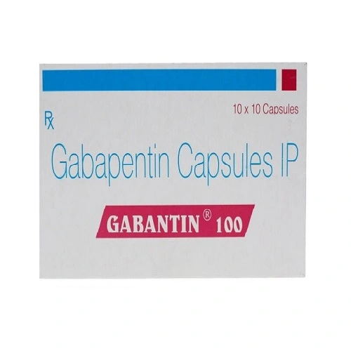
Mar 12, 2025Everything You Should Know About Gabantin 100 mg
Mar 12, 2025Where Can One Find a Trustworthy Supplier of
Mar 12, 2025Importance of the best trade show exhibit booths
Mar 12, 2025The Rise of Political Podcasts: Stay Informed and
Mar 12, 2025Where Luxury and Modernity Converge Stussy Fashion
Mar 12, 202511 Factors That Drive Up Swimming Pool Installation
Mar 12, 2025How Do Visa Assistance Service Providers Help You
Mar 12, 2025Hellstar Shirt The Ultimate Statement
Mar 12, 2025Top PhD Thesis Writing Services in India –
Mar 12, 2025Low-Cost Concrete Chute for Any Project – Shop
Mar 12, 2025A Beginner’s Guide to Investing in Liquid Mutual
Mar 12, 2025Importance of PR Agency in Healthcare Sector
Mar 12, 2025What are the best possible investment options in
Mar 12, 2025Elevate Your Home with Nibav Home Elevators
Mar 12, 2025Best Destination Wedding Spots in Allahabad for 2025
Mar 12, 2025What is Daman Online Game and how does
Mar 12, 2025How to Keep Your E-Bikes Running Smoothly with
Mar 12, 2025The Thrill of Axe Throwing: A Modern Adventure
Mar 12, 2025Get Expert Excel Assignment Help – Fast &
Mar 11, 2025The Ultimate Guide to Broken Planet T-Shirts: Style
Mar 11, 2025The Ultimate Guide to GV Gallery Pants
Mar 11, 2025“Essentials Hoodie | Fear Of God Essential Australia
Mar 11, 2025Boost Your Freelance Business with a Scalable Fiverr
Mar 11, 2025Why Rotary Lobe Pumps Are Preferred for Viscous
Mar 11, 2025What Are The Top Benefits of Using Indian
Mar 11, 2025What is the On Board Weighing System Price
Mar 11, 2025How to Hire an Illustrator for Corporate Branding
Mar 11, 2025Why is Sourcing Certification Important in 2025?
Mar 11, 2025Damaged Cars for Sale NJ: Your Guide to
Mar 11, 2025How to Choose the Best Boba Toppings for
Mar 11, 2025What are the most important tips that you
Mar 11, 2025How to Choose the Best Dubai Lights Manufacturers
Mar 11, 2025What to Consider When Selecting an Aircraft Charter
Mar 11, 2025Wrecked Car Auction Tips: How to Get the
Mar 11, 2025Car Fame: Your Destination for New Car For
Mar 11, 2025What Are the Most Effective Squirrel Removal Methods
Mar 11, 2025The Best Dove Hunting Gear for Women: A
Mar 11, 2025Top Surgical Instruments Shop in Lahore
Mar 11, 2025Top Google Ads Agency : Unlocking Success with
Mar 11, 2025A Comprehensive Guide to Lighting Installation
Mar 11, 2025Top Digital Marketing Agency in UAE for Business
Mar 11, 2025Air Ticketing Course in Rawalpindi Islamabad
Mar 11, 2025Al Karama: Exploring the Vibrant Heart of Dubai
Mar 11, 2025“Essentials Hoodie | Fear Of God Essential Australia
Mar 11, 2025A Comfortable Moving Journey from Delhi to Bangalore
Mar 11, 2025What Are 3PL Companies in Canada? A Beginner’s
Mar 11, 2025How to Build a Firearm Emergency Kit for
Mar 11, 2025Fall Fashion: Essentials Hoodie Layering Guide
Mar 11, 2025Civil Lab Technician Course In Rawalpindi-Islamabad
Mar 11, 2025Everything You Need To Know About Cement Bulker
Mar 11, 2025Exploring the Hype Behind the Felpa Stone Island
Mar 11, 2025What Are the Key Benefits of Using Local
Mar 11, 2025Best Rooftop Solar Panels in India | Rooftop
Mar 11, 2025How Python Became The Go-To Language for Programmers
Mar 11, 2025The Ultimate Guide to the Hellstar Hoodie
Mar 11, 2025Why Every Fashion Lover Needs a BAPE Hoodie
Mar 11, 2025Help by Virtual Medical Administrative Assistant
Mar 11, 2025Hellstar The Rising Star of Streetwear
Mar 10, 2025Best SEO Packages in India – DigitalGrow4u
Mar 10, 2025Why ISO 27001 Certification Is Crucial for Your
Mar 10, 2025Back Pain Management Guide: 7 Natural Tips for
Mar 10, 2025The History Behind Dsquared2’s Streetwear Staple
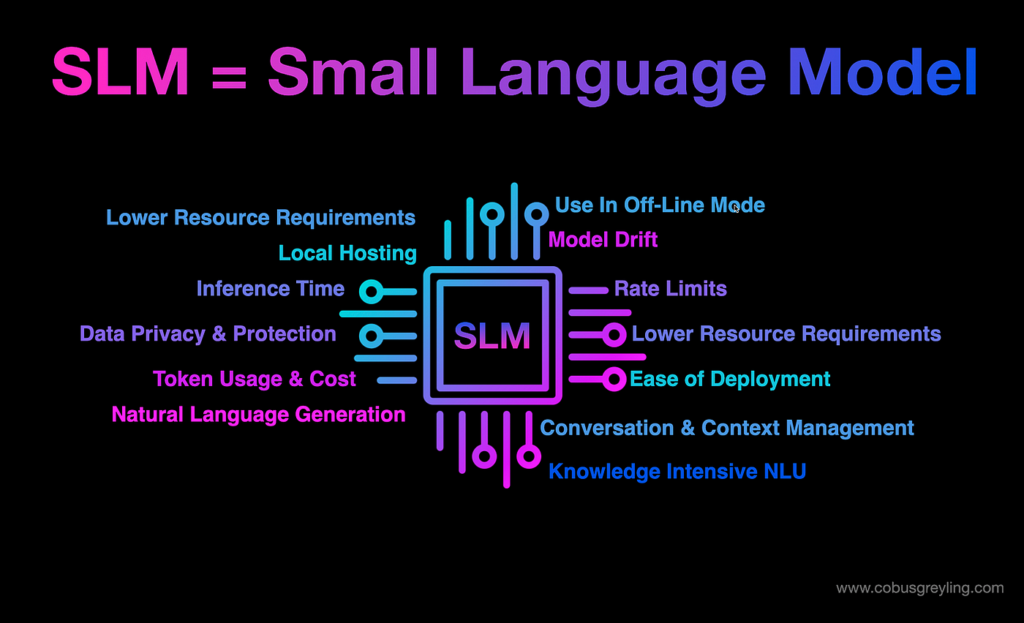
Mar 10, 2025Small Language Models: The Future of Efficient and
Mar 10, 2025What Tools and Platforms Are Covered in a
Mar 10, 2025What is nail art and courses to become
Mar 10, 20255 Proven to Reduce Claim Rejections and Improve
Mar 10, 2025Which is the best IELTS coaching center in
Mar 10, 2025What are the types of flex printing?
Mar 10, 2025Steps to Become an Educator with a Diploma
Mar 10, 2025How Legal Professionals Are Using AI Checker to
Mar 10, 2025Top-Rated CCNA Courses for Networking Professionals
Mar 10, 2025Hire Smart Contract Developers
Mar 10, 2025Discovering The Best Cab Service in London
Mar 10, 2025Enhance Your Bathroom with Stylish Accessories
Mar 10, 2025How to Choose the Best Block Paving for
Mar 10, 2025Apple iPhone 17 Pro Max Design: New Leak
Mar 10, 2025The Future of Employee Experience: Trends to Watch
Mar 10, 2025The Ultimate Guide to Playboi Carti Concert Tees
Mar 10, 2025The Untold Story of Khalistan Shaheed and Their
Mar 10, 2025How Wooden Sash Window Decoration Boosts Kerb Appeal
Mar 10, 2025Your Ultimate Guide to Equipping Your Home with
Mar 10, 2025Butter vs. Ghee vs. Oil: Which One is
Mar 10, 2025A Guide to Choosing an Affordable Aged Care
Mar 10, 2025Differences Between Square Tubing And Other Types Of
Mar 10, 2025The Top 2 Lash Services in Texas: Elevate
Mar 10, 2025Car Rentals in Brisbane: A Comprehensive Review of
Mar 09, 2025How to Increase Internet Speed
Mar 09, 2025Black Essentials Hoodie The Ultimate Blend
Mar 09, 2025Leading Audit Firms in Dubai for Business Compliance
Mar 09, 2025Corteiz Tracksuit The Ultimate Blend of Style
Mar 09, 2025Maui Kayak Tours in 2025: What’s New and
Mar 09, 2025The Ultimate Guide to Spider Hoodie: The Trend
Mar 09, 2025The Ultimate Guide to King-Size Bed Dimensions
Mar 08, 2025RideX Ltd – Reliable and Luxurious Private Hire
Mar 08, 2025Nasha Mukti Kendra /Diya Welfare
Mar 08, 2025Bosch | Power, Precision, and Performance for Every
Mar 08, 2025Why You Should Tailor Your CV for Every
Mar 08, 2025The 10 Most Beautiful Places to Visit in
Mar 08, 2025Reasons to Choose the Best Carpet Repair Services
Mar 08, 2025What Qualifies as a Truly Luxurious Villa
Mar 08, 2025Sleek and Smart: Modern Standard Lamps and Motion
Mar 08, 2025The Best Dishes to Try When Ordering Food
Mar 07, 2025Why It’s Important to Have Friends Outside of
Mar 07, 2025The Importance of VAT Return Filing Services in
Mar 07, 2025Essential VAT Tax Services Every Business Needs to
Mar 07, 2025Why Quality Ankle Socks Make All the Difference
Mar 07, 2025Mistakes to Avoid When Choosing the Best Hydrogel
Mar 07, 2025Explore ICAD Abu Dhabi – The Future of
Mar 07, 2025Why Al Nasr Plaza Residence is the Ideal
Mar 07, 2025Enhancing Security for Business and Compliance
Mar 07, 2025The luxurious jewelry brands of Pakistan: Where to
Mar 07, 2025Power of Custom Development Services
Mar 07, 2025Your Trusted Source for Genuine Products in Dubai
Mar 07, 2025Why V Boards Are a Must-Have for Roadside
Mar 07, 2025What Makes Shan-A-Punjab a Must-Try in Boston
Mar 07, 2025Top Study Abroad Advisor in Dubai for Seamless
Mar 07, 2025How Online Nursing Tutors Can Help You in
Mar 07, 2025How LED Strip Lighting Can Transform Your Home:
Mar 07, 2025Where Can I Find the Best Deals on
Mar 07, 202510 Reasons Why Hiring Direct Tax Consultants is
Mar 07, 2025Comfort And Convenience: The Key To Ideal Living
Mar 07, 2025Can you help me choose a research topic
Mar 07, 2025A Guide to Choosing the Right ORM Services
Mar 07, 2025How to Style Your Golf Outfit with a
Mar 07, 2025Enhance Your Space with a Durable Cable Railing
Mar 07, 2025Fast Water Softener System Repair You Can Trust
Mar 07, 2025Steps to Successfully Trade in Your Old Device
Mar 06, 2025Elementor #13497
Mar 06, 2025The Ultimate Guide to Choosing the Right PPC
Mar 06, 2025Where to get the best diamond rings for
Mar 06, 2025Exploring the Ethical Challenges of Generative AI
Mar 06, 20257 Important tips that you need to know
Mar 06, 2025Where to Find the Best Diagnostic Labs Near
Mar 06, 2025How Can a Group Online Chess Course Help
Mar 06, 202513 Hong Kong Tips Every First-Time Traveler Should
Mar 06, 202510 Things to Consider When Choosing an Online
Mar 06, 2025Leading Web Development Companies Nearby
Mar 06, 2025Quantum AI Market Demand, Suppliers And Forecasts To
Mar 06, 2025The Role and Importance of an Electrical Contractor
Mar 06, 2025Uses of Felted Wool in B2B Markets: A
Mar 06, 2025Why Managed IT Services Are a Game-Changer for
Mar 06, 2025Crafting an Effective Literature Review: A How-To
Mar 06, 2025Keep Your Skin Rejuvenate with Hydrafacial in Los
Mar 06, 2025Benefits of Hiring a Full Stack Developer
Mar 06, 2025How a Liverpool SEO Agency Can Boost Your
Mar 06, 2025Tips to Choose the Best BMW Service Nearby
Mar 06, 2025Hire a Law Assignment Writer for Top-Notch Law
Mar 06, 2025Why Al Muwaileh Sharjah is a Great Place
Mar 06, 2025After-School Programs for Special Needs: A Guide for
Mar 06, 2025Top Hair Extensions Ontario & Wigs for Hair
Mar 06, 2025Why Homeowners Love French Doors for Elegance
Mar 06, 2025Best Cricket Gears Shops Near Me & Online
Mar 06, 20255 Tips for Health Policy Comparison
Mar 06, 2025Wooden Furniture Online – A Timeless Elegance for
Mar 06, 2025What Are the Benefits of Offices for Rent
Mar 06, 2025What Is a Windows Dedicated Server?
Mar 06, 2025Best Rhinoplasty & Liposuction Surgeons in Mumbai
Mar 06, 2025Reasons to Buy Refurbished Water Well Drilling Rigs
Mar 06, 2025Discover the Oppo A3 Price in Pakistan for
Mar 06, 2025Leading Door and Window Manufacturers – A Detailed
Mar 06, 2025Common Roofing Problems in Florida and How to
Mar 06, 2025Do My Coursework: The Ultimate Guide to Getting
Mar 06, 2025What is Google Workspace’s Business Standard Plan?
Mar 06, 2025Stussy Hoodie: The Ultimate Guide to Style, Care
Mar 06, 2025Al Khawaneej Dubai – A Blend of Tradition
Mar 06, 2025Can a tax accountant in Preston understand my
Mar 06, 2025How can you grab the best deal while
Mar 06, 2025Microsoft Dynamics 365 Partners in UAE: Benefits &
Mar 06, 2025Affordable CT Scan Price in Bangalore – Procedure
Mar 06, 2025EEG Test in Bangalore | Procedure, Cost, and
Mar 06, 2025Convenient & Safe Blood Sample Collection from Home
Mar 06, 2025What is the Time of Pagoda Visit?
Mar 06, 2025Why Car Paint Repair Is Essential In Dubai’s
Mar 06, 2025Best Cleaning Products for Deep Cleaning Your Home
Mar 05, 2025DAFZA Approved Auditors: Ensuring Compliance
Mar 05, 2025Top Digital Marketing Agencies in India and Dubai
Mar 05, 2025Best Cafr in Deira City Center: A Coffee
Mar 05, 2025Top Hair Coloring Techniques Every Color Hair Salon
Mar 05, 2025Custom Software Development Services
Mar 05, 2025Finding Justice: Why You Need a Phoenix Truck
Mar 05, 2025Male Fertility and IVF: How an IVF Center
Mar 05, 2025Popeyes Menu: A Complete Guide to Their Delicious
Mar 05, 2025Boost Business with Pay Per Click Manchester: A
Mar 05, 2025Is Leaking Transmission Fluid a Sign of a
Mar 05, 2025How Businesses Succeed with TikTok Ads & Marketing
Mar 05, 2025Kamdhenu Cow: An important symbol of Vastu and
Mar 05, 2025A Guide To Choose The Right Golf Grips
Mar 05, 2025How to Choose the Right Dubai Free Zone
Mar 05, 2025How SEO Helps Businesses Increase Online Visibility
Mar 05, 2025Can General Auto Repair Service Extend the Life
Mar 05, 2025How to Choose the Right Electricity Provider for
Mar 05, 2025How to Set Up a Separate Network for
Mar 05, 2025Purple Jeans: The Ultimate Style Statement
Mar 05, 2025The Weight of Sleep: How Obesity & Sleep
Mar 05, 2025How Bus Ticket Booking Apps Can Reduce Overcrowding
Mar 05, 2025The Growing Appeal of Women Pret in Modern
Mar 05, 2025How Small and Medium Enterprises Can Profit from
Mar 05, 2025Top Furniture Supplier in India – Your Ultimate
Mar 05, 2025Expert Piano Movers in JVC Dubai for a
Mar 05, 2025Lederhosen: A Timeless Tradition of Bavarian Culture
Mar 05, 2025How to Assess the Quality Standards of a
Mar 05, 2025Is Your Car Battery Service Overdue? Signs You
Mar 05, 2025Why Blackout Roller Blinds Are Perfect for Nurseries
Mar 05, 2025Conveyor Belt Maintenance: Do’s and Don’ts
Mar 05, 2025Reliable Villa Movers and Packers in Dubai
Mar 05, 2025Hellstar Clothing: A Blend of Comfort, Style, and
Mar 05, 2025How Can I Attract More Indian Followers to
Mar 05, 2025Lahore Smart City Rates – 2025 Overview
Mar 05, 2025“What Makes Lahore Smart City Different?”
Mar 05, 2025Get Yours Before It’s Gone – Slump Cone
Mar 05, 2025Best Conditioners to Prevent & Stronger Hair Loss
Mar 05, 2025Essay Writing Hacks for Exam Success
Mar 05, 2025Protect Welding Systems with Accurate Leak Detection
Mar 05, 2025Send Fresh Flower in Cyprus With Fast &
Mar 05, 2025How to Build a Profitable E-Commerce Website for
Mar 05, 2025SEO vs. Paid Ads: What’s Best for Your
Mar 05, 2025When Should You See an ENT About Your
Mar 05, 2025A Minimally Invasive Option for Chronic Sinusitis
Mar 05, 2025The Impact of Antibiotics on Pet Gut Health
Mar 04, 2025Hands-Free vs. Traditional Leashes: What’s Best?
Mar 04, 2025Mercier Clothing: The Ultimate Blend of Luxury and
Mar 04, 2025Discover Top Quality Home Cabinets Near Me In
Mar 04, 2025How to Incorporate Wooden Elements in Stair Design
Mar 04, 2025A Comprehensive Review for Photography Enthusiasts
Mar 04, 2025Navigating Georgia’s Personal Injury Laws
Mar 04, 2025Find Quality Home Cabinets Near Me Today
Mar 04, 2025Find Affordable Flood Repair in Kansas City
Mar 04, 2025Chicago Flood Cleanup Experts Protect Your Home
Mar 04, 2025Does a Cheap Windows VPS Affect SEO? Everything
Mar 04, 2025How to Apply Setting Powder Over Hydrating Primer
Mar 04, 2025AI Inside: The Secret Sauce Behind The Smartest
Mar 04, 2025Chronic Pain in Athletes: Specialized Care Options
Mar 04, 2025Inside the Marriage of David Nelson and Kelsi
Mar 04, 2025How Azure Cloud Services in UAE Boost Business
Mar 04, 2025How to Choose the Right SEO Agency for
Mar 04, 2025Best Practices for Dissertation Writing in 2025
Mar 04, 2025Mastering Primary 4 Maths and Preparing for PSLE
Mar 04, 2025Modern Glass Pool Fencing: A Sleek and Safe
Mar 04, 2025Develop Zillow Clone Real Estate App | From
Mar 04, 2025Understanding CMA USA: Full Form and Duration
Mar 04, 2025Tapaday 200 for Back Pain: Its Benefits, Risks,
Mar 04, 2025Timeless Elegance: Hand Block Print Kurtas for Every
Mar 04, 2025What to Expect from the Upcoming Movie’s Duration
Mar 04, 2025Mastering Math Puzzles and Boosting Your Channel
Mar 04, 2025How to Personalize Your Game Safely and Creatively
Mar 04, 2025Pull Stussy: A Streetwear Must-Have
Mar 04, 2025The Role of AI in Bank Statement Analysis
Mar 04, 2025Expert Tips from Cover Letter Writers Dubai for
Mar 04, 2025BTEC Assignment Help in Dubai: Your Ultimate Guide
Mar 04, 2025Elevating Your Brand with Lip Balm Packaging
Mar 04, 2025Rudrabhishek Puja in Ujjain: A Comprehensive Guide
Mar 04, 2025The Art of Goodbye In Goodbye Cards
Mar 04, 2025“Lahore Smart City: The Most Exciting Real Estate
Mar 04, 2025How to Stretch for Muscle Relief
Mar 04, 2025Apple iPhone 8 Plus in Australia: Classic Design
Mar 04, 2025Callable Bonds: Prepare for Early Redemption Risks
Mar 04, 2025“Lahore Smart City Rates: What’s Driving the Surge
Mar 04, 2025Can ivermectin cause skin problems?
Mar 04, 2025Cyber Law in Sweden: Key Legal Aspects of
Mar 04, 2025Home Used Cars for Sale in Ghana –
Mar 04, 2025AI-Powered Guest Post Services for Better Outreach
Mar 04, 2025The Booming Logistics Industry in Dubai: A Hub
Mar 04, 2025Atlanta SEO Services Providers for Local Businesses
Mar 04, 2025Travis Scott Official Store – Hoodies, Tees, &
Mar 04, 2025Top 10 Most-Visited Attractions in South Africa
Mar 04, 2025KBH Gamer: The Ultimate Guide to Gaming Excellence
Mar 04, 2025Krunker.io Cheats: Everything You Need to Know in
Mar 04, 2025Simple Jeem Lawn Dresses Elegance and Comfort
Mar 04, 2025JM Used Auto Spare Parts – Quality Used
Mar 04, 2025How Argus Silent Pet Tags Keep Your Furry
Mar 04, 2025Navigating with Ease: Ultimate Guide to Taxi Service
Mar 03, 2025Understanding the Cost: A Guide to Makkah to
Mar 03, 2025How Long Do You Have to Sell a
Mar 03, 2025The Art of Crafting Unique Platinum Jewelry: Best
Mar 03, 2025Bosch Refrigerator Repair: Common Problems
Mar 03, 2025TYPO3 vs WordPress: Which CMS is Right for
Mar 03, 2025Worried About Real Estate App Security? What You
Mar 03, 2025Best Turkey Holidays 2025 & Sri Lanka Unforgettable
Mar 03, 2025Zingyzon | Your Online Earning Helper
Mar 03, 2025How to Arrange Group Transportation to Cruise Port
Mar 03, 2025Why End Life Molded Pulp is the Future
Mar 03, 2025Luxury Streetwear: Cole Buxton’s Hoodies You Need
Mar 03, 2025How Expert Marketing Assignment Help Boosts Your GPA
Mar 03, 2025Best Garage Door Repair Houston – BBM Garage
Mar 03, 2025Avoid Mistakes! Learn How to Write Discussion Post
Mar 03, 2025Oversized & Cozy: Why Big Hoodies Are Still
Mar 03, 2025Fast Cake Delivery – Send Cakes to Karachi
Mar 03, 2025NEBOSH Course in Rawalpindi Islamabad
Mar 03, 2025Best Umrah Packages and Umrah Deals for a
Mar 03, 2025Transform Your Office with the Best Furniture
Mar 03, 2025Best Free WordPress Themes for Business and Personal
Mar 03, 2025How Ergonomic Office Furniture Enhances Productivity
Mar 03, 2025Hoodies are a famous thing of dress for
Mar 03, 2025Custom Office Furniture for Unique Business Needs
Mar 03, 2025Why a Swivel Chair is a Must-Have for
Mar 03, 2025Get the Stussy Hoodie Look – Official Website,
Mar 03, 2025RIVINGTON roi Rebis : Sustainability at the Core
Mar 03, 2025Elegant Bakery WordPress Themes to Build Your Online
Mar 03, 2025Best Redmi Mobile Price in Pakistan for Every
Mar 03, 2025Lifeguard Skills in 2025: What Employers Are Looking
Mar 03, 2025Right Office Chair for Comfort and Productivity
Mar 03, 2025Factors to Consider When Selecting Office Furniture
Mar 03, 2025Invest in the Best Office Furniture for a
Mar 03, 2025Why an L Shape Sofa is the Perfect
Mar 03, 2025Choosing the Right Office Table for Your Needs
Mar 03, 2025Why You Need Study Abroad Consultants in Dubai
Mar 03, 2025Why is Sp5der Clothing Taking the Fashion World
Mar 03, 2025How to Leverage a USA Consumer Email List
Mar 03, 2025Nike Hoodie: The Ultimate Blend of Style and
Mar 03, 2025What Are the Features of Top-Quality Coursework Help
Mar 03, 2025A Major Initiative for Rural Employment in India
Mar 03, 2025Official Broken Planet Market – Secure & Easy
Mar 03, 2025Broken Planet The Struggles and Consequences of a
Mar 03, 2025Von Dutch: The Rise Fall and Resurgence of
Mar 03, 2025Maximizing ROI with Google Shopping Feed and Local
Mar 03, 2025TAFE Assignment Help: A Guide for Students
Mar 03, 2025Chrome Hearts Bracelet A Blend of Luxury and
Mar 03, 2025Zach Bryan Merch: The Ultimate Guide for Fans
Mar 03, 2025Chrome Hearts Hoodie A Fashion Statement of Luxury
Mar 03, 2025OVO Clothing: A Deep Dive into the Iconic
Mar 03, 2025SP5DER Hoodie A Blend of Style Comfort and
Mar 03, 2025Eric Emanuel Short A Blend of Style Comfort
Mar 03, 2025The Weeknd Merch: A Deep Dive into the
Mar 03, 2025Is iPhone 14 Pro Worth It for Streaming
Mar 03, 2025Essentials of Gods A Deep Dive Into the
Mar 03, 2025Exploring the Build and Durability of Samsung A05s
Mar 03, 2025Vlone x Playboi Carti The Intersection of Fashion
Mar 03, 2025Cotton Dresses: The Epitome of Comfort and Elegance
Mar 03, 2025The Weeknd After Hours T-Shirt Fans and Streetwear
Mar 03, 2025Golf Wang Casual T-Shirt Blend of Streetwear and
Mar 03, 2025Display Counter for Your Bakery
Mar 03, 2025Ladies Diamond Pendants – Exquisite Craftsmanship
Mar 03, 2025GV Gallery | Minimalist Fashion for Timeless Style
Mar 03, 2025Basketcase Gallery: A Deep Dive into the Underground
Mar 02, 2025Syna Wrld Tracksuit: The Ultimate Blend of Comfort
Mar 01, 2025PI123: What It Is and How It Works
Mar 01, 2025What is Meta App Manager? A Simple Guide
Mar 01, 2025Best Ways to Find CNA Jobs You’ll Love
Mar 01, 2025Viral Rock Paper Scissors Yellow Dress: A Trend
Mar 01, 2025How Many Days Are Sufficient for Srisailam?
Mar 01, 2025LIVS Apple Cider Vinegar Gummies: A Natural Solution
Mar 01, 2025GV GALLERY || TheGv Gallery Shop || Official
Feb 28, 2025Corteiz ® | CRTZRTW Official Website || Sale
Feb 28, 2025Why the Essentials Hoodie Feels So Premium
Feb 28, 2025Corteiz ® | CRTZRTW Official Website || Sale
Feb 28, 2025What is Nuclear Energy and How Does It
Feb 28, 2025Ecommerce Development Services
Feb 28, 2025Oplaadtijd voor JNR Media Max 40000: Hoe lang
Feb 28, 2025Temps de charge pour JNR Media Max 40000
Feb 28, 2025Best CUET Coaching in Delhi – Personalized Learning
Feb 28, 2025Essential Features to Look for in Beauty Salon
Feb 28, 2025Why Decision-Makers Should Take a Power BI Training
Feb 28, 2025LIVS Apple Cider Vinegar Gummies: A Natural Solution
Feb 27, 2025Getting Cozy in Style: The Unexpected Luxury of
Feb 27, 2025Unleashing the Potential of Your Facebook Page with
Feb 27, 2025How to Select the Best Sea View Apartment
Feb 27, 2025Avoiding Accidents: Why Every Dog Needs a High
Feb 27, 2025Essential Features to Look for in the Best
Feb 27, 2025Top Benefits of Using a Thermal Night Scope
Feb 27, 2025The Global Hot Drinks Market: Trends and Future
Feb 27, 2025Say Goodbye to Sugar Disease – Meet The
Feb 27, 2025Corteiz | Cortiez Crtzrtw Official Website | CRTZ
Feb 27, 2025The Long Bob Wig: A Perfect Blend of
Feb 27, 2025Bring Nature to Life with This Stunning Dragonfly
Feb 27, 2025Golf Wang: A Deep Dive Into Its Influence
Feb 26, 2025Top Causes of UAE Vehicle Engine Failure &
Feb 26, 2025Lace Front Wigs: The Ultimate Guide to Caring
Feb 26, 2025Best Pod Kits: Elevate Your Vaping Game
Feb 26, 2025Umfassende Haushaltsauflösung Ahaus mit Plakolli
Feb 26, 2025The Story Behind the Iconic Lucky Me, I
Feb 26, 2025Badson clothing & Sp5der Clothing Famous Clothing Of
Feb 25, 2025Cortiez Cargos: Versatile Pants for Every Season
Feb 25, 2025Best Ecommerce ROI Calculator for UAE Businesses in
Feb 25, 2025Best Home Water Tank Cooling Systems for UAE
Feb 25, 2025From Chill Days to City Nights – Essentials
Feb 25, 2025The History of Syna World: From Idea to
Feb 25, 2025The Surprising Symptoms of Lack of Sleep
Feb 25, 2025Fear of God Essentials Clothing – A Statement
Feb 25, 2025Stay Ahead in Fashion with Corteiz
Feb 25, 2025Made for Comfort: Essentials Hoodie – The Perfect
Feb 25, 2025Hellstar: Elevate Your Streetwear Game Today
Feb 25, 2025How to Choose the Best Security Guard Company
Feb 25, 2025La comparaison ultime entre le RandM Tornado 7000
Feb 25, 2025Why Choose Luxury Car Rental for Your Special
Feb 25, 2025Content Decay: How to Refresh Old Content for
Feb 24, 2025How Fast Can Car Key Replacement Be Done
Feb 24, 2025Looking Ahead to 2025: Marketing Trends Based on
Feb 24, 2025Everything You Need to Know About ELUX Nic
Feb 24, 2025Broken Planet shop and shorts
Feb 24, 2025Atlas Pro IPTV: Your Gateway to Ultimate Streaming
Feb 24, 2025What Is An Asian Bean? A Comprehensive Guide
Feb 23, 2025How to Write a Tech Guest Post That
Feb 23, 2025Experienced Asian Lawyer in Las Vegas – Michael
Feb 22, 2025Bathroom Renovations Guide: How to Plan and Prepare
Feb 22, 2025Stüssy Tees: A Timeless Streetwear Icon in the
Feb 22, 2025Natural Tips for High Blood Pressure: Supplements to
Feb 20, 2025Living with Psoriasis: Skincare Tips for Flare-Ups
Feb 19, 2025Reasons that make Austin Limo Service Unavoidable
Feb 19, 2025Reasons to Buy Bike Tyres Online
Feb 18, 2025Best Online Deals: Your Ultimate Guide to Smart
Feb 18, 2025Get 40% Off Broken Planet Market’s Best-Sellers!
Feb 17, 2025Is Cortiez the Best Kept Secret in Fashion?
Feb 17, 2025Why Are Comfortable Bottoms and Shorts a Must-Have
Feb 17, 2025SEO: A Game Changer for Entrepreneurs and Business
Feb 17, 2025Lavender Chamomile Tea: A Natural Remedy for Stress
Feb 17, 2025Prop Firms: Unlocking the Path to Consistent and
Feb 17, 2025How Affordable Are Apartments for Rent in Lusail?
Feb 17, 2025Mitolyn Review: Can This Supplement Truly Aid Weight
Feb 17, 2025How Can Love My Shot Help You Achieve
Feb 17, 2025Mitolyn Review: Does This Really Help with Weight
Feb 17, 2025What Should You Wear for a Family Photoshoot
Feb 17, 2025WordPress maintenance services
Feb 17, 2025How Can Car Rental in New Jersey Enhance
Feb 17, 2025Mitolyn Review: Is It Effective for Weight Loss?
Feb 17, 2025List of top aluminium doors windows manufacturers in
Feb 17, 2025Top Features to Look for in Men’s Safety
Feb 17, 2025Hellstar Tracksuit, Where Comfort Meets Elegance
Feb 17, 2025What are Unsecured Personal Loans and How to
Feb 17, 2025Solitaire – Play Free Solitaire Card Games Online
Feb 17, 2025Connections Game & Nerdle by NYT Unlimited Daily
Feb 17, 2025Mini Crossword & Quordle – Daily NYT Word
Feb 17, 2025Enterprise Risk Management (ERM): What It Is and
Feb 17, 2025Spelling Bee & Strands: NYT Words and Theme
Feb 17, 2025Sudoku & Mahjong Online – Solve Web Sudoku
Feb 17, 2025What is the Qualification of a Driving Instructor?
Feb 17, 2025How to Sell Silver Bar UK Online for
Feb 17, 2025A Key to Maximizing Tax Benefits for Property
Feb 17, 2025Best Mirrors for Wedding Signs – Add Elegance
Feb 17, 2025How to Get Unlimited Lives on Gardenscapes:
Feb 17, 2025Common Mistakes to Avoid on the Hardest Difficulty
Feb 17, 2025How to Save Time & Money on Car
Feb 17, 2025Best RC Planes for Beginners 2025 | Easy
Feb 17, 2025Why IV Hydration Vitamin Therapy New Trend in
Feb 17, 2025Mortgage Broker Services in Calgary: How They Help
Feb 16, 2025How Long Does Degree Attestation Take in the
Feb 15, 2025Wordle: Play Free Today Unlimited NYT Word Game
Feb 15, 2025Elementor #11018
Feb 15, 2025The Ultimate Guide to the Essentials Hoodie: A
Feb 15, 2025How Can HR Data Analytics Enhance Employee Retention
Feb 15, 2025The Ultimate Guide to the Spider Hoodie: Fashion,
Feb 15, 2025RAZ LTX 25K Zero Nicotine: A New Standard
Feb 15, 2025The Auction Marketplace Changing How We Buy
Feb 15, 2025Generate Your Google Review Link with This Free
Feb 15, 2025Stay Ahead of Trends with Broken Planet Market
Feb 14, 2025Syna World UK: Streetwear Meets Culture with Central
Feb 14, 2025Last Chance to Own This Cortiez Drop!
Feb 14, 2025Why Everyone Is Talking About Hellstar Fashion
Feb 14, 2025MVP Development Services for Startups
Feb 14, 2025SightCare for Eye Health: A Comprehensive Guide
Feb 14, 2025Expert Tips for the Perfect Essay Professional Essay
Feb 14, 2025Top Denim Tears Pieces You Need in Your
Feb 14, 2025Cooking Course In Rawalpindi Islamabad
Feb 14, 2025The Best Sp5der Hoodie for Everyday Style in
Feb 14, 2025A Guide to Choosing the Best Watches for
Feb 14, 2025ProDentim for Dental Health: Improved Oral Hygiene
Feb 14, 2025What Happens During an MOT Test?
Feb 14, 2025Day Crawler Raz: A Fresh Start for Your
Feb 14, 2025Essentials Hoodie Review Is It Worth the Hype
Feb 13, 2025Dentist in DHA Lahore: Expert Dental Care for
Feb 13, 2025Chrome Hearts Sweatpants Review: Are They Worth the
Feb 13, 2025Top Free Local Business Listing Sites in Pakistan
Feb 13, 2025A Complete Guide to Personal Injury Claims in
Feb 13, 2025Mitolyn Review Does It Really Work for Weight
Feb 13, 2025MCom Distance Learning: Admission Open in IGNOU
Feb 13, 2025Breeze Vapes: A Game-Changer in the Vaping World
Feb 13, 2025Why Payroll Outsourcing Services are Essential
Feb 13, 20258 Reasons Why You Should Choose Physiotherapy as
Feb 13, 2025How to Elevate Your Desserts with Ubet Chocolate
Feb 13, 20257 Secret Signs Your Car’s Transmission Needs Urgent
Feb 13, 2025The Rich Aromas of Bharara King Fragrance That
Feb 13, 2025The Influence of SonyaMasse on Modern Trends
Feb 13, 2025Best Elevator Company in India: Nibav Home Lifts
Feb 13, 2025CIBIL Score Check Online: A Guide to Free
Feb 13, 2025Safe and Reliable Packers and Movers Bangalore to
Feb 13, 2025Expert Car Battery Replacement Services in the UAE
Feb 13, 2025Essential Hoodie Effortless Fashion for Every Season
Feb 13, 2025Famity Homez – The Best PG in Laxmi
Feb 13, 2025The Power of Sidebar Backlinks in SEO: A
Feb 13, 2025Gabor Wigs for Women: A Perfect Blend of
Feb 13, 2025How Tyre Innovation Enhances The Safety Of The
Feb 13, 2025Things that Make Routine Car Servicing Important
Feb 13, 2025What is BBA in Digital Marketing and Why
Feb 13, 2025Why Monitoring PF Interest Rates Is Crucial
Feb 13, 2025Cap Printing: A Creative Way to Personalize and
Feb 12, 2025Kado Bar: A Premium Disposable Vape Experience
Feb 12, 2025Varsity Jackets; The Best Staple
Feb 12, 2025Elementor #10642
Feb 12, 2025Essentials Hoodie Blend of Comfort style
Feb 12, 20255 Signs You Need To Hire A Food
Feb 12, 2025Make Your Big Day Magical Wedding Transportation in
Feb 12, 2025How to Conduct a Trademark Search Before Registering
Feb 12, 20258 Ways for Students to Earn Money Online
Feb 12, 2025Decoding Return of Premium in Term Plans
Feb 12, 2025How To Choose the Right Tyres for Your
Feb 12, 2025Loan Against Mutual Funds: 5 Must-Know Features for
Feb 12, 2025Pointers to Keep in Mind While Buying Tyres
Feb 12, 2025Choosing The Best Up And Down Wall Lights
Feb 12, 2025Quality, Comfort, and Trust: Real Estate Company in
Feb 12, 2025SME Loans: Benefits, Eligibility And Documentation
Feb 12, 2025British Airways Refund Policy – Full Guide &
Feb 12, 2025Top Reasons To Choose Chauffeur Services In London
Feb 12, 2025Spider Hoodie Official Sp5der Clothing Online
Feb 12, 2025“Everything You Need to Know About ASAP Roof
Feb 11, 2025Using a West Chicago Limousine Service will Help
Feb 11, 2025Understanding Investment Fund Management Companies
Feb 11, 2025To Invest or Not to Invest in Mobile
Feb 11, 2025A Complete Guide to Travel from Kathgodam to
Feb 11, 2025Why the Syna World Tracksuit Is Dominating the
Feb 11, 2025How To Ensure Quality Car Servicing?
Feb 11, 2025How the Denim Tears Hoodie Redefines Everyday Style
Feb 11, 2025Stay Fit & Healthy: Intermittent Fasting For Women
Feb 11, 2025How Mobile Tyres Have Made An Impact On
Feb 11, 2025Need a Divorce Lawyer in Dubai? Get Expert
Feb 11, 2025Explore the services of AirOfficeHub
Feb 11, 2025Top 10 Ideas: How to Choose Colors for
Feb 11, 2025Deep House Cleaning Services in Irving, TX –
Feb 11, 2025New Construction Company in Oakley, UT – Build
Feb 11, 2025Discover the Refreshing Blue Razz Ice Raz Vape
Feb 10, 2025Professional Drywall Contractors in Kansas City, MO
Feb 10, 2025A Strategic Guide For Designing Mobile App Logos
Feb 10, 2025How an Odoo Partner Can Transform Your Business
Feb 10, 2025What Are the Best Flower Colors for Valentine’s?
Feb 10, 2025How To Know If A Garage Is Good?
Feb 10, 2025Is Vape Price in Pakistan Affordable in 2025?
Feb 10, 2025Top DBMS Assignment Hacks That Will Make You
Feb 10, 2025Why the Rolex GMT-Master II is the Best
Feb 10, 2025How to Use SEM to Attract Customers and
Feb 10, 2025Empowering Your Business for Success: The Role of
Feb 10, 2025Get High-Quality HR MBA Project Reports at Solve
Feb 10, 2025Free Accounting Software for Trust in India
Feb 10, 2025Finance Project Report for MBA 2025 – A
Feb 10, 2025How to Scale Your E-commerce Business with Online
Feb 10, 2025Looking for the Best SEO Company in India?
Feb 10, 2025The Benefits of Hiring a Landscape Designer for
Feb 10, 2025High-Quality LED Lighting Solutions in Dubai & UAE
Feb 10, 2025Consent at Every Step: A Guide to Ethical
Feb 10, 2025Are Drinks Free On Qatar Airways? Everything You
Feb 10, 2025Choosing the Best Contractor for Home Improvement
Feb 10, 2025How to Choose the Perfect Sofa Set Design
Feb 10, 2025How to Find the Best Accounting Assignment Help
Feb 09, 2025Embrace the Elegance of the Carsicko Jacket
Feb 08, 2025Your Top Choice for IT Staff Augmentation Services
Feb 08, 2025The Classic Style and Prestige of Fur Clothing
Feb 08, 2025Future of iOS App Development: Trends and Best
Feb 07, 2025Discover the Spider Pants, A Must Have for
Feb 07, 2025The Hellstar Hoodie piece of clothing for comfort
Feb 07, 2025Fear of God Essentials collection
Feb 07, 2025The Essentials Hoodie from Fear of God
Feb 07, 2025Top Mobile App Development Company Trends for 2025
Feb 07, 2025Premium Management Assignment Help
Feb 07, 2025What Happens if I Miss My Flight on
Feb 07, 2025Vitamin C Retinol Serum The One Product You
Feb 07, 2025Online Commercial Law Assignment Help Australia
Feb 07, 2025How to Crack IIT JAM Mathematics? Best Coaching
Feb 07, 2025India vs England Cricket Rivalry: A Historic Battle
Feb 07, 2025Eric Emanuel Shorts: A Trend in Fashion
Feb 07, 2025Jaipur’s Most Unique Boutique Stays
Feb 07, 2025Top PhD Thesis Writing Services in India –
Feb 07, 2025Solve Zone: Your Trusted Partner for Assignment Help
Feb 07, 2025Top 5 Induction Stove Brands in India: The
Feb 07, 2025The Secret to Building a Website That Brings
Feb 07, 2025How Do I Know If Shockwave Therapy Is
Feb 07, 2025Get Quality MCA Live Transfer Leads for More
Feb 06, 2025Where to Buy Authentic Pop Smoke Merch: A
Feb 06, 2025Is It Better to Rent or Buy a
Feb 06, 2025How Columbus SEO Company Will Shape Digital Success
Feb 06, 2025Charcoal Clay Scrub and Foaming Face Wash by
Feb 06, 2025Maximizing Roi With An Eye-Catching Banner For Trade
Feb 06, 2025Official WWE Championship Replica Belts
Feb 06, 2025Apkstick: Your Ultimate Guide to Apps, APKs, and
Feb 06, 2025Network Detection and Response (NDR) and Why It
Feb 06, 2025How to Participate in Political Polls Online?
Feb 06, 2025Why is IFZA One of the Fastest-Growing Free
Feb 06, 2025Avoid These Costly Notary Mistakes Provided
Feb 06, 2025Arabic Course for Kids: A Engaging Way to
Feb 06, 2025Why Regularly Checking Tubeless Tyre Air Pressure Is
Feb 06, 2025Corteiz Clothing – The Ultimate Streetwear Brand for
Feb 06, 2025What Should You Know Before Buying Summer Tyres?
Feb 06, 202510 Places to Visit in Oman, Tourist Places
Feb 06, 2025How to Keep Up with Rapid Technological Changes
Feb 06, 2025Which is the best Nasha Mukti Kendra in
Feb 06, 2025Step by step instructions to Style Your VLONE
Feb 06, 2025The Top 5 Benefits of Using a Personalized
Feb 05, 2025The Top 10 Ways to Style a Satin
Feb 05, 2025What Makes Attestation Services the Best Option for
Feb 05, 2025Top Mistakes to Avoid During Degree Attestation in
Feb 05, 2025The Pros and Cons of Gas Combi Boilers
Feb 05, 2025The Evolution of Adwysd Clothing
Feb 05, 2025Stussy Clothing A Streetwear Icon
Feb 05, 2025syna world Comfort and Style
Feb 05, 2025Sp5der Hoodie USA Fashion
Feb 05, 2025Home Wound Care Services: Ensuring Healing at Home
Feb 05, 2025Shopify Website Development Company: ROI Hunt
Feb 05, 2025Top 10 IoT App Development Companies
Feb 05, 2025How Physiotherapy Can Help with Work-Related Neck &
Feb 05, 2025The Role of Term Plans in Strengthening Your
Feb 05, 2025Uncover the Ultimate Beauty Journey at Shades of
Feb 05, 2025Rent a Two-Wheeler in Jaipur: A Complete Guide
Feb 05, 2025How MS Plates Are Used in Oil and
Feb 05, 2025How Global Teams Can Transform Your Online Presence
Feb 05, 2025OnlyFans Clone: Your Ticket to the Creator Economy
Feb 05, 2025The Ultimate Guide to Commercial Warmer Steam Tables
Feb 05, 2025What Advantages Do All-season Tyres Offer?
Feb 04, 2025Tips For Maintaining A Polished Floor Finish
Feb 04, 2025How To Remove Mold From Shower Curtain
Feb 04, 2025How To Remove Burnt Odor From Microwave Oven
Feb 04, 2025When Should You Call A Professional For Boiler
Feb 04, 2025How To Remove Pet Odor From Couch?
Feb 04, 2025How To Remove Kitchen Musty Odors?
Feb 04, 2025How Long Does Floor Wax Last After Application?
Feb 04, 2025The Best Places To Display A USA Flag
Feb 04, 2025IPTV SMARTERS PRO: The Ultimate Streaming Solution
Feb 04, 2025Drip IV Hydration: Instant Relief from Dehydration &
Feb 04, 2025Why Should You Use Summer Tyres?
Feb 04, 20254 Best Winter Car Tyres You Should Check
Feb 04, 2025A Perfect Manali Trip from Hyderabad!
Feb 04, 2025Top App Development Companies 2024
Feb 04, 2025How to Choose the Best White Label SEO
Feb 04, 2025Simplifying Complex Concepts: A Six-Step Guide
Feb 04, 2025Best MBA College in Jaipur with Highest Placement
Feb 04, 2025Data Center in India: Why Noida is a
Feb 04, 2025Hair Toppers for Women: A Stylish Solution for
Feb 04, 2025Best YouTube to MP4 Converters
Feb 04, 2025How to Assess Warehouse Providers for Seasonal Needs
Feb 04, 2025Sell Old Electronics for Instant Cash
Feb 04, 2025“A Comprehensive Guide to Textile Dyes and Their
Feb 03, 2025How Shipping Mailers Can Save You Money &
Feb 03, 2025Plumbing in Dubai: Reliable Services for Every Home
Feb 03, 2025The Power of Abstract Logo Design — Logo
Feb 03, 2025The Power of Abstract Logo Design — Logo
Feb 03, 2025Travel Without Hassle and at Affordable Prices
Feb 03, 2025Luxury & Strength: 10 Must-Have Platinum Rings for
Feb 03, 2025Fast and Professional Assignment Help Services
Feb 03, 2025The Cost of Installing a 10 kW Solar
Feb 03, 2025Epilepsy Seizure Action Plan: Step-by-Step Guide
Feb 03, 2025Hair Loss Treatments That You Need to Know
Feb 03, 2025Car Dash Cams – HD Mirror Cam and
Feb 03, 2025Explore Dubai’s Modern Wonders: A City Tour Guide
Feb 03, 2025Aline Insoles vs Superfeet: Top Thermal Inserts For
Feb 03, 2025How Do Automatic Tie Balers Save Time and
Feb 03, 2025The Smart Way to Outsource Accounting to India
Feb 03, 2025Innovate Fearlessly – Welcome to Syna World.
Feb 02, 2025How to Choose the Best ACCA Institute in
Feb 02, 2025Essentials Clothing – Simple, Stylish, Essential
Feb 01, 2025Discover the Difference with Broken Planet Market
Feb 01, 2025Cortiez Fashion Trends You Need to Know
Feb 01, 2025Go Fearless. Go Hellstar.
Feb 01, 2025Exploring the Success of BriansClub: A Hub for
Feb 01, 2025We Buy Junk Cars: Turn Clutter into Cash
Feb 01, 20252048 by Gabriele Cirulli • Play the Free
Feb 01, 2025Dice Roller | Online Virtual Dice for Gaming
Feb 01, 2025Wheel of Names | Random Name Picker Online
Feb 01, 2025Top 5 Clothing Brands Defining Modern Fashion Trends
Feb 01, 2025Coin Flip – Flip a Coin to Get
Feb 01, 2025Need an Apostille in Orange County? Don’t Make
Feb 01, 2025Expert Tips for Car AC Repair and Maintenance
Feb 01, 2025Vehicle Care Tips for Keeping Your Car in
Feb 01, 2025How is Virtual Reality transforming Real Estate?
Feb 01, 2025The Ultimate Guide to Buying Wholesale Clothes in
Feb 01, 2025JMK Florist: Trusted Flower Delivery Service Calgary
Feb 01, 2025Airport Transfer services in New York
Jan 31, 2025How Automation Enhances Patient Care Quality
Jan 31, 2025Optimize Your Facebook Ad Campaigns Today
Jan 31, 2025Why 80,000+ Members Trust 1% Club For Their
Jan 31, 2025Top 10 Use Cases for Generative AI Models
Jan 31, 2025Corteiz Pop-Up Stores What Makes Them So Iconic?
Jan 31, 2025The Impact of Web Design on User Behavior
Jan 30, 2025How Can You Personalize Outdoor Spaces with Custom
Jan 30, 2025Top 2D Animation Company | Split Arts Technologies
Jan 30, 2025NRI Mutual Fund Taxation: A Comprehensive Overview
Jan 30, 2025SAE Extension Cord :The Key to Seamless Power
Jan 30, 20255 Critical Steps to Developing a Powerful Marketing
Jan 30, 2025Shopify SEO Specialist: How to Rank Higher &
Jan 30, 2025Timeless Beauty: White Pearl Embellished Clutch
Jan 30, 2025Is Investing in White Label PPC Beneficial for
Jan 30, 20255 Reasons Redmi Note 14 Pro Plus Is
Jan 30, 2025The 6 Best Beaches in Kerala for a
Jan 30, 2025Latest Trends in Process Compliance
Jan 30, 2025Why Professional Car Window Tinting in Dubai Matters
Jan 30, 2025Why Salesforce Managed Services is an Admin’s Best
Jan 30, 2025Insta Pro APK Download Latest Version for Android
Jan 29, 2025Pizza Qatar: Top Picks for Every Food Lover
Jan 29, 2025Tips for Shopping at Lee Cooper Stores in
Jan 29, 2025Breathe Without Limits – Dr. Sanchayan Roy as
Jan 29, 2025Optimize Your Website with the Best SearchGPT SEO
Jan 29, 2025Why PlayStation 5 is the Future of Gaming
Jan 29, 2025A Guide to Uniform Suppliers in Dubai
Jan 29, 2025MERN-Stack Training: Building A Student’s IT Career
Jan 29, 2025The Importance of Technology in Modern 3PL Logistics
Jan 29, 2025Why Online Assignment Help is a Game-Changer for
Jan 29, 2025The Ultimate Sushi Restaurant Experience in Qatar
Jan 29, 2025Expert Car Recovery Service in Abu Dhabi for
Jan 29, 2025Auto Electrician course in Rawalpindi
Jan 29, 2025Mistakes to Avoid When Hiring a Divorce Lawyer
Jan 29, 2025How to Handle a Tax Warrant: Essential Steps
Jan 29, 2025How to Hire Dedicated Developers for Outsourced IT
Jan 28, 2025Difference Between A2 Ghee and Clarified Butter
Jan 28, 2025Microfinance loans: What it is, Types, and Examples
Jan 28, 2025How Much Do Digital Signage Boards Cost to
Jan 28, 2025Expert Home Inspections in Miami-Dade
Jan 28, 2025How Healing Centers Help You Overcome Stress and
Jan 28, 2025Curtains and Blinds in Dubai: How to Choose
Jan 28, 2025Why Steel Suppliers Are Key to Sustainable Building
Jan 28, 2025Everything You Need to Know About Crystal Prime
Jan 28, 2025The Popularity of Cortiez and Corteiz Tracksuits
Jan 28, 2025Styling the Combo of Essentials Hoodie & Essentials
Jan 28, 2025The Role of the HbA1c Test in Diagnosing
Jan 28, 2025Rubber Bar Mat Manufacturer: Custom Bar Mats
Jan 28, 2025Top & Advanced Digital Marketing Courses in Model
Jan 27, 2025Notary Public in Edina: Your Guide to Notary
Jan 27, 2025Comprehensive Guide to Hosting Services in Pakistan
Jan 27, 2025Affordable Makkah to Jeddah Taxi Fare for Your
Jan 27, 2025Avtube: Revolutionizing the Digital Era
Jan 27, 2025Skilled Criminal Defense Lawyer in Cumming, Georgia
Jan 27, 2025Real Estate Company in Pune for Luxury Affordable
Jan 27, 2025Bhutan Travel Tips: What to Know Before You
Jan 27, 2025Trapstar Tracksuit: A Must-Have for Streetwear
Jan 27, 2025The Broken Planet Hoodie – A Must-Have for
Jan 27, 2025Make Your Wardrobe with Corteiz Cargos
Jan 27, 2025Hand Block Printed Razai Crafted for Peaceful Sleep
Jan 27, 2025Wauconda Heating and Air Conditioning
Jan 27, 2025Expert Google Ads Management in Abu Dhabi
Jan 27, 2025Non Woven Fabric Manufacturers in India
Jan 27, 2025How to Compare Medicare Costs and Coverage in
Jan 27, 2025Discover the Power of Atlas Pro ONTV: The
Jan 27, 2025How to Select Bedroom Sets for Dubai Homes
Jan 25, 2025Buy Instagram Views in Australia
Jan 25, 2025The Ultimate Guide to Spider Hoodies: Style Meets
Jan 25, 2025The Best Handmade Viking Axe in USA
Jan 25, 2025Finding the Right General Contractors Near You: A
Jan 25, 2025Miguel Harichi: Age, Height, Wiki, Bio, Net Worth,
Jan 25, 2025Top Skills You’ll Learn in a CNC Programming
Jan 24, 2025Cortiez Shop And Hoodie
Jan 24, 2025Everything You Need to Know about How to
Jan 24, 2025Top White Label SEO Strategies for Lead Generation
Jan 24, 2025Is Skin Tag Removal in Dubai Worth It?
Jan 24, 2025How to Navigate Me Bhoomi for Accurate Land
Jan 24, 2025MAP: Trusted Wealth and Asset Management Services in
Jan 24, 2025Which Hair Color will Look Good for Brown
Jan 24, 2025Your Ultimate Guide to Calculating Taxes Like a
Jan 24, 2025How SEO is Evolving in 2025
Jan 24, 2025Transform Your Space: The Power of the Icon
Jan 24, 2025Explore the Timeless Appeal of Shaker Style Doors
Jan 24, 2025The Evolution of Online Learning
Jan 23, 2025Can’t Afford a Lawyer? Try Pakistan Law Bot
Jan 23, 2025Which Hair Color will Look Good for Brown
Jan 23, 2025Cortiez and Corteiz Tracksuits Are Taking Over the
Jan 23, 2025Maulana Maududi’s Impact on Global Islamic Movements
Jan 23, 2025The Essentials Hoodie and Essentials Tracksuit
Jan 23, 2025Study in Australia: A Guide to Living and
Jan 23, 2025What are the Tax Implications of Ethical Audits
Jan 23, 2025Spacious The Tote Bag That Guarantees Style and
Jan 23, 2025Rental Limousine Cars Your Ultimate Lift for Any
Jan 23, 2025Italian Finger Foods That Will Steal the Show
Jan 22, 2025Why Hellstar clothing is the Ultimate Choice.
Jan 22, 2025Why Cortiez Shorts Are a Must-Have for Every
Jan 22, 2025How to Improve Your On-Page SEO Skills for
Jan 22, 2025Who are the Common Users of German Translation?
Jan 22, 2025Digital Marketing Agency Boost Your Online Presence
Jan 21, 2025Why Security Doors Are Essential for Home Safety
Jan 21, 2025Discover Your Perfect Smile at the Best Dental
Jan 21, 2025Aadhaar Card for NRIs: A Detailed Assistance
Jan 21, 2025Features of Reliable Marine Exhaust Sprayheads
Jan 21, 2025Premium Properties Offering Modern Urban Comforts
Jan 21, 2025Daily Flash & Empowerment How Brands Can Leverage
Jan 21, 2025Triple Lift Molecule Mask Radiance & Confidence for
Jan 21, 2025The Benefits of SaaS Loan Management Systems
Jan 21, 2025Business Bay: The Ultimate Hub for Luxury Living
Jan 21, 2025Accessorizing Your Summer Skirt: The Ultimate Guide
Jan 21, 2025A Simple Guide to Concrete Installation in NYC
Jan 21, 2025Wondering How to Stay Up-to-Date on Closure Wig
Jan 21, 2025Tech-Savvy Celebrities: Hobbies in Coding and Gaming
Jan 20, 2025Adventurous Hobbies of the Rich and Famous
Jan 20, 2025“The Business of Sports: How Athletes Are Turning
Jan 20, 2025Hollywood Stars Who Are Bookworms at Heart
Jan 20, 2025Hollywood’s Love Affair with Yoga and Meditation
Jan 20, 2025Adrenaline Junkies: Extreme Hobbies of the Stars
Jan 20, 2025Why Hiring an Estate Planning Lawyer in Ontario
Jan 20, 2025THE RPS LLC Your Best Partner for Printing
Jan 20, 2025Winter Fashion Trends in Pakistan You Need to
Jan 20, 2025Benefits of Scale Models in Dubai Real Estate
Jan 20, 2025Do You Know You Can Save Up to
Jan 20, 2025Your Ultimate Modest Fashion Guide
Jan 20, 2025Future Trends: The Evolution of Design Patterns in
Jan 20, 2025How to Apply for an Indian Tourist Visa
Jan 20, 2025How should I take oxandrolone?
Jan 20, 2025Top 9 Attractions to See on Your Darjeeling
Jan 20, 2025Building Estimating Services UK
Jan 20, 2025Knitting Bags & Totes How They Make Crafting
Jan 20, 2025Protect London || Protect LDN Official Website ||
Jan 19, 2025Discover Dubai with a Mercedes or Lamborghini Rental
Jan 19, 2025How Do Chemical Beakers Differ from Regular Glass
Jan 18, 2025Premium Bath Bomb Boxes for Ultimate Protection
Jan 18, 2025Best Digital Marketing Courses After 10th: A Pathway
Jan 18, 2025Best Sugar Stocks in India: A Sweet Opportunity
Jan 18, 2025Expert Guide to Car Fuel Pump Repair and
Jan 18, 2025Tech Behind Juwa 777: Key Software Providers &
Jan 18, 2025Benefits of renting Ferrari F8 Spider and BMW
Jan 18, 2025Choosing the Right Corner Cabinet Sizes for Your
Jan 18, 2025Popular Courses to Study in UK for Indian
Jan 17, 2025How Drama-Based Learning Sparks Creativity in Teams
Jan 17, 2025Essentials Hoodie : Redefining Everyday Fashion
Jan 17, 2025Sp5der Hoodie Popular USA Brand
Jan 16, 2025Discover Dubai: Renting a Chevrolet vs. Ford rental
Jan 16, 2025Degree Attestation in UAE: A Complete Guide
Jan 16, 2025Degree Attestation in UAE: A Complete Guide
Jan 16, 2025The Ultimate Guide to Abayas, Kaftan Gowns, and
Jan 16, 2025Medical Degree in Georgia: Your Path to Global
Jan 16, 2025How To Choose The Right Surgeon For Your
Jan 16, 2025Housekeeping and Security Guard Company in Delhi
Jan 16, 2025Comprehensive Guide to IELTS, OET, and PTE Coaching
Jan 16, 2025Top 6 Places to Visit in Argentina: A
Jan 16, 2025Fingerprinting Myths vs. Reality in Los Angeles
Jan 16, 20258 Interesting Facts About the Czech Republic
Jan 16, 2025Top 6 Places to Visit in Jaipur: A
Jan 16, 2025Regulatory Changes for NBFCs: What’s New in 2025?
Jan 16, 2025Haval H6 TPU Interior PPF – Scratch Resistance
Jan 16, 2025How Much Does E-Commerce Website Development Cost in
Jan 16, 2025Why Businesses in Surat Need E-Commerce Web and
Jan 16, 2025Broken Planet Shop And Broken Planet Hoodie
Jan 16, 2025How to Use 3D Product Animation in Email
Jan 15, 2025Top Benefits of Hiring a Data Analyst Company
Jan 15, 2025How to Master Product Sorting WooCommerce for Better
Jan 15, 2025Do’s and Don’ts for Maintaining Your Car Engine
Jan 15, 2025Top 6 Must-Do activities in Dubai
Jan 15, 2025The Ultimate Guide to Mixing and Matching Fashion
Jan 15, 2025Custom Vape Boxes: A Smart Strategy for Vape
Jan 14, 2025Type of Property to Qualify for GBIS
Jan 14, 2025The Ultimate Guide to Choosing the Right Kobalt
Jan 14, 2025Top Property Valuation Companies in Westbourne
Jan 14, 2025Affordable Garage Door Services in Sunningdale
Jan 14, 202524/7 Emergency Boiler Repairs Southampton
Jan 14, 2025Real Estate Developers in Delhi NCR | KREEVA
Jan 14, 2025Streamlining User Experience for Store Admins
Jan 14, 2025A Powerful Incentive for Increased Sales
Jan 14, 2025Boost Sales with Strategic Pricing Offers
Jan 14, 2025The Rise of 2D and 3D Animation Services
Jan 14, 2025Consistency in Graphic Design: Why It Matters for
Jan 14, 2025How Thesis Help Can Elevate Your Research and
Jan 14, 2025WooCommerce Purchase Notification: Boost Sales
Jan 14, 2025Hide Shipping Method for WooCommerce Plugin
Jan 14, 2025Top Finance Push Ads Trends in North Korea
Jan 14, 2025Top Education Marketing Platform Trends in 2025
Jan 14, 2025Why Every Business Needs a Cybersecurity Partner in
Jan 14, 2025How to Develop Your Brand and Become an
Jan 14, 2025Introduction to Minustwo Jeans
Jan 14, 2025How to Choose the Right Bulk SMS Service
Jan 14, 2025Celebrities Seen Wearing Hellstar Sweatpants
Jan 14, 2025Study in USA for Indian students after 12th
Jan 14, 2025Savor the Flavors of China: Traditional Dishes and
Jan 14, 2025What You Need to Know About Sewage Water
Jan 14, 2025Savor the Flavors of China: Traditional Dishes and
Jan 14, 2025Design Your Dream Home with a Custom-Built Staircase
Jan 13, 2025commedesgarconsclothing Official Online Store
Jan 13, 2025Achieve Perfect Dental Alignment with The Tooth Care
Jan 13, 2025dragon ball fighterz download pc ✓ Get Full
Jan 01, 2023uc browser free download for pc ✓ Fast
Jan 01, 2023Trending Topics
commedesgarconsclothing Official Online Store
Celebrities Seen Wearing Hellstar Sweatpants
Introduction to Minustwo Jeans
Mechanical estimating services for heating and cooling systems
commedesgarconsclothing Official Online Store
Celebrities Seen Wearing Hellstar Sweatpants
Introduction to Minustwo Jeans
Mechanical estimating services for heating and cooling systems
commedesgarconsclothing Official Online Store
Celebrities Seen Wearing Hellstar Sweatpants
Introduction to Minustwo Jeans
Title: Top Online Game Genres to Watch in 2025
Mechanical estimating services for heating and cooling systems
Celebrities Seen Wearing Hellstar Sweatpants
Most Reading
Get Latest News from Online Tech Learner
Published Video
Download GB WhatsApp APK – Updated Version (2025)
GV GALLERY® || Raspberry Hills Clothing Store || Shop Now
Hiring Digital Marketing Company in Toronto: Smart Business Move
- The Art of Luxury Interiors: A Journey into Elegance and Comfort
- May 01, 2025
Top Castles and Palaces to Visit in Hungary
Mechanical estimating services for heating and cooling systems
International News
The Secret to Ultimate Relaxation: Russian Spa Services in Dwarka
Trending Topics
Achieve Perfect Dental Alignment with The Tooth Care in Gurgaon
NehaTheToothCareMechanical estimating services for heating and cooling systems
precisionestimatorcommedesgarconsclothing Official Online Store
The Art of Luxury Interiors: A Journey into Elegance and ComfortAchieve Perfect Dental Alignment with The Tooth Care in Gurgaon
NehaTheToothCareMechanical estimating services for heating and cooling systems
precisionestimatorcommedesgarconsclothing Official Online Store
The Art of Luxury Interiors: A Journey into Elegance and ComfortAchieve Perfect Dental Alignment with The Tooth Care in Gurgaon
NehaTheToothCare- # Tags
- Evan Bass Men's Clinic
Evan Bass Men’s Clinic Discusses the Importance of Father-Child Bond and Relationship
Bonding and spending time with their father is important to the overall development of a child. As per Evan Bass
-
admin / 2 months
- 0
- 3 min read
- # Tags
- Charles Spinelli
Charles Spinelli Unlocks the Secrets of Designing a Competitive Employee Benefits Package
Attracting and retaining top talent in a business is the key to maintaining a competitive edge according to Charles Spinelli.
-
admin / 2 months
- 0
- 3 min read
- # Tags
- Scott Tominaga
What to Expect from a Financial Advisor in the First 90 Days: Scott Tominaga
The first 90 days of working with a financial advisor are as vital for the professional as the client. It’s
-
admin / 2 months
- 0
- 3 min read
- # Tags
- Safe Ship Moving Services
Safe Ship Moving Services Discusses Benefits of Using Professional Packing Services
Moving to a new home is quite a stressful and time-consuming endeavour. Preparing for a move involves a myriad of
-
admin / 2 months
- 0
- 3 min read
- # Tags
- Steven Rindner
Steven Rindner On Impact of Weather Conditions in Trail Running- Challenges and Solutions
When it comes to trail running experience, exposure to varying weather conditions is natural. Notably, it is weather that broadly
-
admin / 2 months
- 0
- 3 min read
Is Post-Op IV Ozone Therapy Useful for Joint Recovery?
Post-operative care is a critical aspect of healing, especially when recovering from surgery related to joints. A variety of treatment
-
healthcare333 / 3 months
- 0
- 5 min read
How Do You Take Care of Your Vehicle for Car Servicing and MOT?
It is very important for regular car servicing as it plays a crucial role in the maintenance of safety, ensuring
-
kingsaceautocenter / 3 months
- 0
- 5 min read
How Does Jawline Contouring Injections Sculpt the Face?
In the realm of modern aesthetic enhancements, jawline contouring injections have emerged as a leading non-surgical method to sculpt and
-
healthcare303 / 3 months
- 0
- 5 min read
Does Oxygen Facial Reduce Large Pores Too?
Large pores are a common skincare concern for many people. While not harmful, they can make the skin appear uneven
-
dynamicclinic303 / 3 months
- 0
- 5 min read
- # Tags
- Hellstar Shirt
Discover the Bold Streetwear Power of the Iconic Hellstar Shirt Brand
Hellstar Shirt Offers Unique Style The Hellstar shirt has become a popular choice for people who enjoy bold fashion with
-
zohaib / 3 months
- 0
- 9 min read
- # Tags
- vip travel agency
Choose VIP Travel Agency for Luxury Adventures
Do you fantasize about lounging on a secluded seashore, dwelling in a 5-megastar inn, or flying pleasant luxury? Most people
-
webdesign / 3 months
- 0
- 5 min read
Why Choose HydraFacial for Flawless Skin in Dubai?
In a city known for its luxurious lifestyle and relentless sun exposure, maintaining healthy, radiant skin can be a challenge.
-
healthcare998 / 3 months
- 0
- 3 min read
- # Tags
- bitachon
Bitachon for Beginners: A Quick Guide
In today’s fast-paced and uncertain world, many people are looking for a deeper sense of peace, trust, and purpose. Whether
-
sakibseowork1 / 3 months
- 0
- 7 min read
Top Skin Whitening Treatments in Dubai: A Quick Guide
Dubai, a city known for its luxury, beauty, and innovation, is also a hotbed for cutting-edge skincare treatments. For many,
-
healthcare998 / 3 months
- 0
- 5 min read
Download GB WhatsApp APK – Updated Version (2025)
In 2025, messaging is more than just text—users want control, customization, and privacy. GB WhatsApp delivers all of that and
-
The Art of Luxury Interiors: A Journey into Elegance and Comfort / 3 months
- 0
- 4 min read
Selected News
Charles Spinelli Unlocks the Secrets of Designing a Competitive Employee Benefits Package
What to Expect from a Financial Advisor in the First 90 Days: Scott Tominaga
Safe Ship Moving Services Discusses Benefits of Using Professional Packing Services
Travel Blogs
Top Castles and Palaces to Visit in Hungary
Online Voating

This may be the latest case of post aggression emigration in Ukraine. But it is unlikely to be the final stage for millions of people to leave the country. These people do not want


 English


